Interactive Engineering Sizing & Customization Tool

Custom AGV & AMR Drive Units

Custom AGV & AMR drive units combine wheel, motor, gearbox and mounting interfaces around your robot requirements. Estimate torque and power, compare catalog and custom options, then request an engineering review.

By AMRDriveUnit · Published · Reviewed

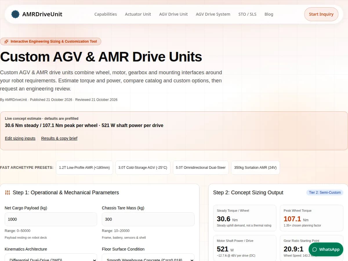
Live concept estimate · defaults are prefilled

30.6 Nm steady / 107.1 Nm peak per wheel · 521 W shaft power per drive

Fast Archetype Presets:
Step 1: Operational & Mechanical Parameters

Range: 0–50000

Payload resting on robot deck

Range: 10–20000

Frame, battery, sensors & shell

Differential dual-drive

Dictates rolling resistance & tire friction

Range: 0.1–5

Cruise velocity

Range: 0.2–10

0 to cruise ramp

Range: 0–35

Ramp climbing angle

Range: 80–600

Tread outer diameter

Range: 100–1000

Chassis envelope ceiling

Battery supply voltage

Duty is a request; this tool does not calculate a thermal rating.

Step 2: Concept Sizing Output
Tier 2: Semi-Custom
Steady Torque / Wheel
30.6 Nm
Steady uphill demand, not a thermal rating
Peak Wheel Torque
107.1 Nm
1.35× chosen planning factor
Motor Shaft Power / Drive
521 W
~12.7 A @ 48V per drive (DC)
Gear Ratio Starting Point
20.9:1
Wheel Speed: 143.2 RPM
Peak DC Current / Drive
44.5 A
Total traction peak: 89 A
Static Holding / Wheel
28.7 Nm
1.5× selected grade; wheel-side estimate
Total Gross Mass:1300 kg
Total Tractive Force:1586.7 N
Force per Drive Wheel:793.3 N
Total Traction DC Current:25.4 A steady
Requested Duty:Requested S1 continuous duty; verify thermal equilibrium with the actual cooling path.
Motor Frame:Not determined: compare supplier torque-speed curves and thermal ratings
Gearbox Candidates:Review inline planetary / integrated steer-drive options
Tread Material:Compare supplier-rated polyurethane / Vulkollan® wheel assemblies
Engineering Bottlenecks Detected:
  • Ramp rollback review required: selecting a safety target does not verify brake holding, stopping performance or adhesion.

Concept assumptions & limits

Equal wheel loading; straight-line uphill travel. Crr 0.018, dry-floor friction 0.65, driven mass fraction 0.6. Replace these with measured route and axle data.

Gearbox efficiency 0.88; motor 0.9; inverter 0.95. Pshaft = torque × angular speed / gearbox efficiency. DC current = Pshaft / (voltage × motor efficiency × inverter efficiency). Auxiliaries and battery sag excluded; DC current is not phase current.

Ratio assumes 3000 motor RPM. The tier is a heuristic review path, not proof that bespoke is required. Check catalog options first.

Stopping distance, scanner fields, wheel contact stress and thermal rating are not determined. Holding torque is at the wheel on the selected grade; zero grade gives zero static estimate. Brake placement, gear losses, redundancy and power-loss behavior need validation.

Review equations and evidence

Next engineering actions

  • Validate power-loss holding and loaded stopping in both slope directions; STO alone does not hold a vehicle.
  • Request supplier torque-speed curves, a CAD envelope and a written validation plan before purchasing.
Copy this brief, then open the inquiry form and paste it into Project Summary.
Decision Framework

Key Engineering Findings: When to Customize AMR Drive Units

Concept design guidance reviewed on 21 October 2026. The equations are planning estimates; manufacturer and standards links below establish their stated scope. No private deployment dataset is claimed.

1. Envelope Compression

Compare the complete wheel and mounting CAD envelope first. A low height target alone does not establish that a catalog unit will fail or bespoke gearing is required. See the packaging comparison below.

2. 48V Bus Efficiency

At equal DC input power and unchanged harness resistance, doubling voltage halves current and quarters harness I²R losses. This algebra does not predict motor heating or battery runtime; compare compatible battery and inverter ratings.

3. Built-in Safety Feedback

Define the required safety functions before selecting feedback and brakes. A safety target, encoder count or STO feature does not verify the complete vehicle. Use the ISO scope links and request configuration-specific evidence.

4. Semi-Custom Sweet Spot

Compare catalog, semi-custom and bespoke options against identical CAD, performance and acceptance requirements. NRE, MOQ and lead time remain unknown until a dated supplier quote is agreed.

Evidence and scope: ISO 13849-1:2023

Reproduce a custom drive unit sizing example

Use the prefilled 1,000 kg payload, 300 kg chassis, two driven wheels, 1.5 m/s speed, 2 s acceleration, 3% grade, 200 mm wheel and 48 V bus. With the disclosed dry-concrete and efficiency assumptions, the tool returns 30.6 Nm steady torque and 107.1 Nm peak planning torque per wheel, plus 521 W steady shaft power per drive. Change the inputs above to explore the effect on your concept.

Custom AGV and AMR drive units calculator with default inputs and concept torque and power results
Actual tool screenshot, captured 21 October 2026. This is reproducible software evidence; it does not represent a physical drive test, customer deployment or certified load rating.
Engineering Mechanics

Kinematic Force Balance & Free-Body Equilibrium

First-principles physical model illustrating tractive force distribution, rolling resistance, grade inclination force, and acceleration inertia against the chassis height envelope.

AMR Drive Unit Kinematics & Force Equilibrium ModelGrade Angle θ (Incline %)Vehicle Gross Mass (M = M_payload + M_chassis)Center of Gravity (CG)Custom Drive Wheel (D)Castor WheelHeight Envelope (H_max < 200mm)F_tractive = F_roll + F_grade + F_accWeight Force W = M · gF_oppose (F_roll + F_grade)

θ = atan(grade / 100); Froll = M × 9.80665 × Crr × cos θ; Fgrade = M × 9.80665 × sin θ; Faccel = M × v / ramp time.

Steady wheel torque = (Froll + Fgrade) × wheel radius / driven-wheel count. Peak wheel torque = (Froll + Fgrade + Faccel) × wheel radius × 1.35 / driven-wheel count. The chosen 1.35 factor is not a guarantee for scrub, impacts or rotating inertia.

These first-principles equations model straight-line uphill travel with equal load sharing. Supplier torque-speed limits, route RMS torque, descending/regenerative behavior and thermal capacity require separate validation.

Evidence and scope: ISO 3691-4:2023ISO 13849-1:2023

Functional Safety & Kinematics

Stopping Arithmetic & Protective-Field Review Limits

Illustrative level-floor arithmetic only: distance = v × reaction time + v² / (2 × deceleration). Every table row assumes 0.15 s response and 0.80 m/s² deceleration; the final column adds a chosen 0.25 m allowance. These are not ISO-prescribed constants or scanner settings. Actual slope, brake condition, response chain, scan geometry and manufacturer supplements are not modeled.

Stopping arithmetic example; assumptions are not commissioning valuesAMR Chassis (Mass M)Velocity v = 1.5 m/s →LiDARObstacleD_reaction = v · T_total(assumed 150 ms response ≈ 0.23 m)D_braking = v² / (2 · a_decel)(assumed deceleration: 0.8 m/s² ≈ 1.41 m)Margin C_m(chosen allowance = 0.25 m)Illustrative level-floor arithmetic; not an ISO-prescribed field:Example + allowance = (v · T) + [v² / (2 · a)] + 0.25 m

Evidence and scope: ISO 3691-4:2023SICK S300 §4.3.7

Travel Velocity (v)Reaction Lag (150ms)Decel Rate (a)Pure Braking (D_braking)Example Stopping DistanceExample + Chosen 0.25 mAisle Integration Guidance
0.8 m/s0.12 m0.80 m/s² (assumed)0.40 m0.52 m0.77 mLevel-floor arithmetic only. Actual braking and protective fields are not determined; measure the complete vehicle and apply scanner instructions. [SICK S300 §4.3.7]
1.2 m/s0.18 m0.80 m/s² (assumed)0.90 m1.08 m1.33 mLevel-floor arithmetic only. Actual braking and protective fields are not determined; measure the complete vehicle and apply scanner instructions. [SICK S300 §4.3.7]
1.6 m/s0.24 m0.80 m/s² (assumed)1.60 m1.84 m2.09 mLevel-floor arithmetic only. Actual braking and protective fields are not determined; measure the complete vehicle and apply scanner instructions. [SICK S300 §4.3.7]
2.0 m/s0.30 m0.80 m/s² (assumed)2.50 m2.80 m3.05 mLevel-floor arithmetic only. Actual braking and protective fields are not determined; measure the complete vehicle and apply scanner instructions. [SICK S300 §4.3.7]
2.5 m/s0.38 m0.80 m/s² (assumed)3.91 m4.28 m4.53 mLevel-floor arithmetic only. Actual braking and protective fields are not determined; measure the complete vehicle and apply scanner instructions. [SICK S300 §4.3.7]
Procurement & DFM Trade-Offs

Table 1: Standard Catalog COTS vs. Semi-Custom vs. Full Bespoke

Decision criteria for comparing equally scoped options. Commercial values are unknown as of 21 October 2026; N/A means a current written quote or model-specific evidence is required, not a zero cost or lead time.

Engineering DimensionTier 1: Standard COTSTier 2: Semi-Custom ModTier 3: Full Ground-Up BespokeDecision Impact & Advice
PackagingCheck catalog CAD and mounting interfaces first.Review an adapter, motor orientation or shaft change.Consider a new housing only after catalog options fail.Height alone does not determine the required transmission.
NRE and recurring costN/A: current written quote needed.N/A: quote engineering, fixtures and validation separately.N/A: quote tooling, design ownership and validation separately.Compare total project cost = NRE + quantity × unit price + validation + maintenance.
Prototype lead timeN/A: confirm stock and configuration.N/A: confirm drawing approval and machining capacity.N/A: confirm tooling milestones and test duration.Request a dated schedule with acceptance gates; no public lead-time evidence is available.
MOQ and volumeN/A: supplier confirmation required.N/A: agree prototype and production batches separately.N/A: establish tooling amortization and spare-part strategy.No universal annual quantity makes bespoke cheaper; compare written quotes.
Ratio and efficiencyCompare available ratios at the actual torque and speed.Investigate existing gear-stage variants.Request a new ratio and a measured efficiency map.The calculator uses assumed efficiencies, not supplier measurements.
Safety integrationObtain the exact drive and encoder safety documentation.Verify the modified configuration remains within documented limits.Plan component and complete-vehicle validation.An encoder count or customization tier does not establish a performance level. [ISO 13849-1]
EnvironmentCheck temperature, seals and IP evidence for the selected model.Validate connectors, lubricant and condensation control.Agree a dedicated environmental qualification plan.IP ratings do not establish chemical compatibility, cleanroom or freezer suitability.
Selection Workflow

Customization Pathway Decision Logic

Systematic decision logic guiding robotics system architects from operational sizing inputs to a candidate review path. This heuristic does not select a supplier or establish feasibility; compare catalog CAD first.

Custom Drive Unit Engineering Selection FlowchartSystem SizingPayload, Speed, InclineReview CAD fitAll constraintsCompare catalog CADCOTS Fit Catalog?Ratio & Flange MatchYesTier 1: Standard Catalog COTSQuote, availability and MOQ requiredNo (Minor mod required)Tier 2: Semi-Custom ModExisting platform changes; quote requiredNew layout needed after catalog reviewTier 3: Full Ground-Up BespokeNew design and validation; quote required
Vehicle Kinematics

Table 2: Mobile Robot Drive Kinematics Comparison

Comparing Differential 2WD, Single Steer-Drive, Dual Steer-Drive, and Quad Swerve architectures in terms of turning radius, odometry stability, and software control complexity.

Kinematic ArchitectureDrive / Steer WheelsTurning KinematicsPayload RangeOdometry StabilityControl ComplexityTarget AMR/AGV Types
Differential dual-drive2 fixed driven wheels plus supportsCan turn in place; support-wheel scrub remains.N/A: assembly and axle ratings requiredAffected by slip and floor contact.Two traction axes; verify kinematic calibration.Evaluate for compact transport with adequate turning clearance.
Single steer-drive1 driven and steered module plus supportsDepends on wheelbase and steering limits.N/A: load distribution requiredRequires steering-angle and traction feedback.Traction and steering coordination.Evaluate for pallet trucks or tuggers with suitable axle loading.
Dual steer-drive2 independently driven and steered modulesCrab and pivot maneuvers depend on geometry.N/A: wheel and bearing ratings requiredSteering error can cause wheel fighting.Coordinated traction and steering axes.Evaluate for long loads that need sideways alignment.
Quad swerve4 independently driven and steered modulesTranslation direction changes need steering motion.N/A: structural and floor limits requiredDepends on suspension and load sharing.Eight axes plus load and slip management.Evaluate when maneuverability justifies added controls and maintenance.
Tribology & Materials

Table 3: Wheel Tread Material Mechanical & Tribological Properties

Material specifications comparing high-grade Vulkollan®, standard polyurethane, ESD conductive compounds, and low-temperature cold-storage polymers.

Tread Material FormulationShore HardnessRolling Coeff. (Crr)Max Load CapacityTear & Gouge ResistanceThermal HysteresisIdeal Industrial Environment
Vulkollan® / NDI polyurethaneGrade-specific; request the finished-wheel specification.N/A: measure for wheel, load and floor.N/A: obtain wheel load-speed-duty rating.Manufacturer reports strong mechanical properties. [Covestro]Low heat buildup is a qualitative material benefit, not a wheel rating.Candidate for demanding dynamic loads; confirm assembly limits.
Cast polyurethaneFormulation-specific.N/A: route pull test needed.N/A: supplier dynamic-load data needed.Verify compound and bond quality.Measure temperature under repeated loaded travel.Compare cost, wear and grip on the actual warehouse floor.
Conductive polyurethaneFormulation-specific.N/A: test the conductive grade.N/A: resistivity does not determine load capacity.Verify after wear and cleaning exposure.Qualification must include temperature and conductivity.Assess ESD needs; this alone does not qualify explosive-atmosphere use.
Cold-temperature treadRequest data at the operating temperature.N/A: cold-floor measurement needed.N/A: request temperature derating.Test low-temperature flexing and bond integrity.Consider freeze-thaw and condensation exposure.Qualify the complete wheel in the intended freezer and transition cycle.

Evidence and scope: Covestro Vulkollan®

Viscoelastic Science

Dynamic Mechanical Thermal Analysis (DMTA) & Tread Delamination

Loss factor (tan δ) depends on compound, temperature and test frequency. The public material overview does not establish universal contact-stress, speed or delamination thresholds. Unknown values below require finished-wheel testing rather than a generic chemistry ranking.

Polymer FormulationLoss Factor (Conditions Required)Max Contact StressMax Continuous SpeedHysteretic Heat BuildupAbrasion ResistancePrimary Robotics Application
NDI polyurethane / Vulkollan®N/A: grade, frequency and temperature needed.N/A: finished-wheel rating needed.N/A: load-speed-duty curve needed.Low heat buildup reported qualitatively. [Covestro]Request the test method and grade.Compare for dynamic-load applications; validate tread and hub bond.
MDI polyurethaneN/A: compound-specific DMTA needed.N/A: no universal material limit.N/A: wheel geometry matters.Measure under the intended route.Request comparable abrasion results.Evaluate grip, cost, wear and thermal behavior together.
TDI polyurethaneN/A: compound-specific DMTA needed.N/A: supplier validation needed.N/A: supplier validation needed.Cannot rank from chemistry alone.Test under comparable conditions.Select by tested wheel performance rather than chemistry alone.
Solid rubberN/A: compound-specific DMTA needed.N/A: wheel rating needed.N/A: load and temperature dependent.Measure rolling losses and temperature.Verify floor compatibility and debris resistance.Consider compliance and shock absorption alongside rolling resistance.

Evidence and scope: Covestro Vulkollan®

Mechanical Transmissions

Table 4: Gearbox Technology Comparison for Mobile Robot Drives

Technical trade-offs between inline planetary, right-angle hypoid, and flat in-wheel cycloidal gearings for low-profile chassis packaging and shock load resistance.

Gearbox TechnologyEfficiencyBacklashRadial Axle LoadEnvelope GeometryShock ResistanceRelative Cost
Inline planetaryN/A: request efficiency map.Model-specific.Check bearing life and combined loads.Coaxial; compare full motor and connector envelope.N/A: documented transient rating required.Obtain comparable quotes.
Right-angle hypoid / bevelN/A: ratio and lubrication dependent.Model-specific.Check output support and mounting stiffness.Motor orientation may help packaging.N/A: verify loaded reversals.Include machining, lubricant and validation costs.
In-wheel / cycloidalN/A: request measured torque-speed map.Verify lost motion under load.Verify rim, bearing and reducer as an assembly.Compare wheel diameter, axial width and heat path.N/A: no universal shock-proof rating.Include serviceability and replacement-wheel costs.
Thermal Engineering

Motor Thermal Review: Duty Cycle & Cooling Requirements

Separate duty type, insulation class, winding temperature rise and cooling. Neither a duty label nor nominal insulation headroom predicts lifetime. IEC now lists the 2026 edition; use the applicable scope and a supplier-rated load cycle. Starting heat may require an S4 or more representative duty assessment.

Thermal rating requires a measured load cycle and supplier dataLoad historyTorque, speed, starts, run/restCooling pathAmbient, airflow, chassis contactMotor dataDuty, temperature rise, insulationCombine inputs → validate winding temperature over the representative routeDuty type does not select insulation class or establish a lifetime multiplier.

Evidence and scope: IEC 60034-1:2026ABB motor thermal guidance

IEC 60034-1 Duty RatingMotion Profile PatternAllowable Temp RiseInsulation RatingEvidence Still RequiredMobile Robot Sizing Rule
S1: continuousConstant load until thermal equilibrium.Use the motor rating and measurement method.Independent of duty type.No lifetime multiplier established.Steady torque is only one input; include route load history and cooling.
S2: short-timeSpecified load duration followed by enough rest to cool.Supplier duration-specific rating required.Independent of duty type.No frame downsizing percentage established.Provide run duration and cooling interval; a charging pause may not fully cool the motor.
S3: intermittent periodicRepeated loaded operation and rest; starting heat is not significant.Supplier cycle-specific rating required.Independent of duty type.Load fraction and cycle duration remain unknown.If starts contribute significant heating, discuss S4 or a representative load profile instead.
S4: intermittent with startingRepeated starting, loaded operation and rest.Requires starting frequency and inertia data.Independent of duty type.No life prediction without thermal aging data.Supply starts per hour, reflected inertia and measured winding temperatures.
Mechanical Integration

Integrated Drive Unit Internal Packaging Architecture

Concept layout illustrating how mounting flange, brake, PMSM brushless motor, precision transmission, and bonded polyurethane rim integrate into a single rugged drive unit.

Custom Integrated Drive Unit Internal Architecture1. Custom Chassis FlangeBespoke bolt PCD & Suspension Pin2. Brake & FeedbackSafety evidence required for exact model3. High-Density PMSM MotorVoltage and thermal rating: confirm model4. Planetary / Hypoid GearingRequest measured performance dataHub AxleBearing type and radial rating: supplier data5. High-Traction Polyurethane / Vulkollan® Bonded Wheel Rim
Hypothetical Design Exercises

Four Design Scenarios: Constraints & Validation Plans

Illustrative scenarios, not customer deployments or measured performance. Numeric values are target inputs. Each scenario identifies what to compare and the evidence still needed before a procurement decision.

Design exercise: low-profile pallet AMR
Hypothetical 1,200 kg payload and 250 kg chassis on dry concrete.
Packaging Envelope: 175 mm overall height; 160 mm wheel target.
Engineering Challenge: Only 15 mm remains above the wheel diameter; flange, clearance and suspension travel need a CAD check.
Candidate Approach: Compare catalog CAD with right-angle and in-wheel concepts. Run the low-profile preset to estimate straight-line torque.
Validation Still Required: Not measured. Validate loaded clearance, winding temperature and duty-cycle torque before choosing a design.
Payload: 1,200 kg payload target
Speed: 1.6 m/s target
Height: 175 mm target
Drive Type: Differential concept
Design exercise: cold-storage AGV
Hypothetical 3,000 kg payload plus 1,200 kg chassis with freezer-to-dock transitions.
Packaging Envelope: 380 mm height and 250 mm wheel targets.
Engineering Challenge: Cold lubricant, tread grip, condensation and battery derating remain unknown.
Candidate Approach: Compare low-temperature component data and run the cold-storage preset; its dry-floor friction assumption excludes ice.
Validation Still Required: Not measured. Require cold-start, freeze-thaw, ingress and loaded braking tests. IP65 alone does not qualify a freezer vehicle.
Payload: 3,000 kg payload target
Speed: 1.2 m/s target
Height: 380 mm target
Drive Type: Single steer concept
Design exercise: long-load transporter
Hypothetical 5,000 kg payload plus 1,500 kg chassis requiring sideways alignment.
Packaging Envelope: 320 mm height and 280 mm wheel targets.
Engineering Challenge: Load sharing, floor pressure and coordinated steering cannot be established by gross mass alone.
Candidate Approach: Run the dual-steer preset, then compare steering geometry, axle loads and supplier wheel ratings.
Validation Still Required: Not measured. Test steering synchronization, loaded reversals, tire temperature and floor compatibility; no positioning accuracy is claimed.
Payload: 5,000 kg payload target
Speed: 1.0 m/s target
Height: 320 mm target
Drive Type: Dual steer concept
Design exercise: cleanroom carrier
Hypothetical precision carrier with contamination and vibration requirements.
Packaging Envelope: 190 mm height target; define payload-interface vibration limits before sourcing.
Engineering Challenge: Sealing and low backlash do not establish particle performance or a cleanroom classification.
Candidate Approach: Request wheel wear, lubricant compatibility and vibration test methods for the complete assembly.
Validation Still Required: Not measured. Agree particle-count, cleaning and vibration acceptance methods with the facility; no ISO cleanroom certification is claimed.
Payload: 250 kg payload target
Speed: 1.4 m/s target
Height: 190 mm target
Drive Type: Differential concept
Quality Assurance

Design for Manufacturing (DFM) & Rigorous Factory Validation

Proposed acceptance-plan topics for your RFQ, not a statement of completed factory tests. Agree test conditions, sampling and limits with the supplier before release.

1. FEA Structural Simulation

Finite Element Analysis (FEA) on gear teeth contact stress, cast aluminum housing deflection, and wheel axle shear margins under an agreed load spectrum including curb, shock and mounting loads.

2. Dyno Dynamometer Testing

Agree dynamometer test coverage for the specified torque-speed efficiency curves, inverter current draw, regenerative braking absorption, and back-EMF symmetry.

3. Thermal Runaway Profiling

Measure winding temperatures at the specified ambient, cooling condition and representative route cycle. Confirm the sensor method, insulation rating and acceptance limit with the motor supplier.

4. Acoustic & Vibration FFT

Agree sound and vibration measurement positions, operating loads, frequency range and acceptance criteria. No universal noise threshold is established here.

5. Environmental Chamber Cycling

Validate the requested ingress conditions and actual temperature transitions. Include shaft seals, connectors, lubricant and condensation; the IP label alone does not qualify the environment.

6. Representative Endurance Test

Agree loaded start-stop-reverse cycles, duration and inspection criteria based on the service profile. Record gear, bearing and tread condition; a cycle count alone does not guarantee service life.

Regulatory Compliance

Regulation (EU) 2023/1230: Partly Completed Machinery (PCM) Interface

Reviewed 21 October 2026: the Machinery Regulation mainly applies from 20 January 2027. Classify the actual delivered configuration; a drive unit is not automatically PCM. Where the Regulation applies, Article 3(10) defines PCM and Annex XI covers assembly instructions. PCM has no CE marking under machinery legislation, while other applicable legislation may require it.

Compliance DimensionAMRDriveUnit PCM BoundaryAMR Integrator (Vehicle OEM) BoundaryStatutory Legal Citation
Classification and timingDetermine whether the delivered configuration is a component, partly completed machinery or machinery.Confirm the supply date and applicable legal route. Main application of the Regulation starts 20 January 2027.Regulation (EU) 2023/1230 Art. 3(10), Art. 54; Directive 2006/42/EC before transition
CE markingPCM has no CE marking under machinery legislation; other applicable legislation may require it.Assess and mark the finished machinery under the applicable legislation.Directive 2006/42/EC Art. 13; Regulation Art. 11, 22, 24
Incorporation documentationFor PCM under the Regulation, prepare technical documentation, an EU declaration of incorporation and assembly instructions.Use supplier documents within complete-machine assessment; they do not replace it.Regulation Art. 11; Annex IV Part B, Annex V Part B, Annex XI
Safety functionsSupply model-specific limits, safety manuals and available certificates.Identify functions and required performance; validate the full control chain and vehicle.ISO 13849-1:2023 methodology; ISO 3691-4:2023 scope
Control and software interfacesDocument firmware, configuration and safety-related integration limits.Assess hazards from control changes and external connections.Regulation Annex III §1.1.9 and §1.2.1; applicability requires project review
Assembly versus operator instructionsProvide assembly instructions for the actual supplied PCM.Provide finished-machine instructions and record verification.Regulation Annex XI (PCM assembly); Annex III §1.7.4 (machine instructions)

Evidence and scope: Regulation (EU) 2023/1230

Technical Q&A

Frequently Asked Questions: Custom Drive Unit Engineering

Detailed engineering answers to critical questions regarding torque calculations, voltage sizing, NRE tooling, functional safety compliance, lead times, and quality certifications.

How are steady and peak wheel torque estimated?

This concept model uses F = M g Crr cos θ + M g sin θ + M v/t and divides force equally among driven wheels. Wheel torque is force × wheel radius; peak torque uses a chosen 1.35 planning factor. Rotating inertia, turning scrub and thermal RMS torque require separate checks.

What does the voltage comparison tell me?

For equal DC input power, doubling voltage halves DC current. At unchanged harness resistance, I²R loss becomes one quarter. This does not establish motor phase current, inverter efficiency or a universal payload threshold for 48 V.

What NRE and lead time should I budget?

Public evidence is insufficient for a reliable project quote. Ask for separate engineering, tooling, unit-price and validation costs plus a dated prototype schedule. Compare catalog, semi-custom and bespoke options at the same annual volume and acceptance criteria.

Does a chassis below 180 mm always require bespoke gearing?

No. Compare complete catalog CAD envelopes, wheel diameter, ground clearance and suspension travel first. Right-angle and in-wheel concepts are candidates when existing layouts fail, but height alone does not determine gear type.

Does selecting PL d or SIL 2 verify functional safety?

No. The selection records a requested target for engineering review. ISO 13849-1 provides a control-system design methodology; the applicable safety functions and required performance need a machine-specific assessment. Encoders and STO do not by themselves validate braking or vehicle safety. [ISO 13849-1; ISO 3691-4]

Which fieldbus should I request?

Provide your controller, required update cycle, feedback objects and safety communication requirements. Ask the supplier to confirm the exact model, firmware and interface files. No fieldbus support or synchronization timing is established by this calculator.

When should I compare Vulkollan® with other treads?

Compare it when dynamic load, rolling loss and heat buildup constrain the application. Covestro describes low energy loss and heat buildup, but these qualitative material benefits do not establish a universal MPa limit or finished-wheel load rating. Obtain load-speed-duty data for the selected wheel. [Covestro]

Which validation evidence should an RFQ request?

Agree dimensional inspection, torque-speed testing, thermal duty, brake holding, ingress, vibration and endurance criteria. Specify test loads, temperatures, sampling and pass/fail limits in the purchase specification. This page does not establish that every supplied unit receives a particular test.

What changes for freezer service?

Request temperature-specific lubricant, seal, encoder, battery and wheel data, including condensation exposure during dock transitions. The cold-storage preset is only a dry-floor concept estimate. Freezer hazards require additional assessment beyond the general scope summarized for ISO 3691-4. [ISO 3691-4]

How is wheel slip screened?

The model compares straight-line force demand with assumed friction × driven-axle normal load. It flags demand above 85% of that illustrative limit. Actual center of gravity, load transfer, suspension, wet floors and ice can change traction; measure them before selecting hardware.

What is the MOQ?

MOQ is not established by public evidence on this page. Request prototype, pilot, recurring and spare-part quantities separately, including tooling ownership and service support. The comparison matrix makes no MOQ commitment.

How do I submit the calculated brief?

Copy the RFQ brief, open the inquiry form and paste it into Project Summary. If clipboard permission is denied, use the labeled manual-copy text area. Include drawings, quantity and your required validation plan; a response time or CAD delivery date must be agreed with engineering.

Can I configure a safety scanner from the stopping example?

No. The report illustrates level-floor arithmetic with chosen response time, deceleration and allowance. The tool does not determine stopping distance or a protective field. Use measured vehicle stopping behavior, the scanner instructions and the complete safety assessment, including geometry and supplements. [SICK S300 §4.3.7]

Does the selected duty type establish a motor thermal rating?

No. S1, S2 and S3 record requested duty patterns. Provide the full load-time cycle, ambient temperature and cooling arrangement, then obtain the motor rating. Insulation class and temperature rise do not imply a fixed lifetime multiplier. IEC lists the 2026 edition of IEC 60034-1 as replacing the 2022 edition. [IEC; ABB]

Is every drive unit partly completed machinery, and who applies CE marking?

Classification depends on the supplied configuration. As reviewed on 21 October 2026, Regulation (EU) 2023/1230 mainly applies from 20 January 2027. For PCM under that Regulation, use Article 3(10), Article 11 and Annex XI assembly instructions. PCM is not CE-marked under machinery legislation, while other applicable legislation may still require CE marking. [EUR-Lex]

Can a tread material eliminate delamination?

No universal guarantee is supported. Compound, wheel geometry, adhesive bond, load, speed, temperature and contamination all matter. Ask for comparable dynamic tests and bond validation; no generic loss-factor or contact-pressure threshold on this page certifies the wheel.

Verification & Authority

Primary Engineering Standards & Research Citations

Direct primary-source links, scope summaries and review dates. Public catalog abstracts do not verify paid clauses or product ratings. Unknown values are disclosed in the comparisons.

Last Verified: 2026-10-21
ISO 3691-4:20232023-06

Driverless industrial trucks and their systems: safety requirements and verification

ISO

Published truck-system safety standard; a revision is in development. The public abstract describes scope and exclusions.

Takeaway: The abstract does not establish a universal reaction time, scanner allowance or safety performance level. Freezer-specific hazards need additional review.
Read primary source
ISO 13849-1:20232023-04

Safety-related parts of control systems: design methodology

ISO

Control-system safety methodology, including integration. The public scope does not prescribe application-specific safety functions or PLr.

Takeaway: A requested PL d target and dual feedback are inputs to assessment, not proof that the complete vehicle complies.
Read primary source
IEC 60034-1:20262026-03-13

Rotating electrical machines: rating and performance

IEC

Edition 15 supersedes the 2022 edition. Use the applicable scope and supplier rating for the selected machine.

Takeaway: The catalog confirms edition status; this report does not claim access to or verification of the complete paid standard.
Read primary source
Regulation (EU) 2023/12302023-06-29; application 2027-01-20

Machinery Regulation: classification, incorporation and application dates

European Parliament and Council / EUR-Lex

Article 3(10) defines PCM; Article 11 sets supplier duties; Annex XI covers assembly instructions. Main application starts 20 January 2027.

Takeaway: Before the transition, assess the Directive 2006/42/EC route. Confirm classification and other applicable CE legislation for the supplied configuration.
Read primary source
Covestro Vulkollan®Undated; accessed 2026-10-21

Vulkollan® material properties and applications

Covestro

Manufacturer overview describes NDI-based elastomers and qualitative dynamic properties.

Takeaway: Low heat buildup is supported qualitatively; universal tan δ, MPa and wheel load-speed limits are not established here.
Read primary source
SICK S300 §4.3.72025-08-19 (8010948/ZD76)

S300 operating instructions: mobile applications

SICK

Scanner-specific instructions describe mobile protective-field planning and response-time dependencies.

Takeaway: Field planning must account for the actual vehicle and scanner configuration. The worked example is not a commissioning setting.
Read primary source
ABB motor thermal guidanceUndated; accessed 2026-10-21

REX615 technical manual: thermal protection settings

ABB

Manufacturer guidance distinguishes ambient temperature, winding temperature rise and insulation class.

Takeaway: Temperature rise and insulation class are separate specifications. Neither establishes an automatic motor-life guarantee.
Read primary source

Ready to Engineer Your Custom AMR Powertrain?

Submit your sizing payload or request an engineering feasibility review. Copy the brief and paste it into Project Summary on the inquiry form. Include your drawings, quantity and validation requirements so engineering can confirm scope, schedule and pricing.

Request NDA terms before sharing confidential drawings. Prototype timing and validation scope require written confirmation.

Related Powertrain & Safety Engineering Resources: