AMR / AGV wheel-side sizing
High torque drive sizing for compact industrial solutions
Estimate torque per powered wheel, wheel speed and mechanical power. Compare compact high-torque industrial drives solutions with clear assumptions and a brief for supplier review.
Request engineering reviewHigh torque drive sizing calculator
Jump to resultsBy AMRDriveUnit · Published · Reviewed
From wheel demand to a compact drive shortlist
Use the estimate to prepare requirements for compact high-torque industrial drives solutions. A catalog rating, duty profile and installation review are still needed to choose a drive.
1. Four decisions before requesting a quote
| Decision | What to do | Basis |
|---|---|---|
| Count the complete load | Use total moving mass; state how many wheels share the tractive effort. | Oriental Motor — AGV sizing tool |
| Match torque with speed | Check the operating point against continuous and intermittent ratings. | maxon — Gear technology, pp. 72–73 |
| Treat allowance as provisional | Validate omitted loads and duty before accepting a drive. | Published equations and exclusions below; no safety approval is inferred. |
| Verify power-off behavior | Request assembly-level backdriving and brake information. | maxon — Self-locking or back drivability |
2. Calculation method and output boundary
This page uses a transparent straight-line force balance. With mass m (kg), gravity g = 9.81 m/s², uphill angle θ, rolling coefficient Crr, acceleration a (m/s²), wheel radius r (m), powered-wheel count N and allowance k:
F = m × [a + g × sin(θ) + Crr × g × cos(θ)]
Wheel torque = F × r / N
Sizing torque = k × F × r / N
Wheel rpm = 60 × v / (2π × r)
Total wheel power = F × v
Steady torque: same calculation with a = 0
Only sizing torque includes the allowance. All numeric limits are supported input ranges, not equipment ratings. The model assumes equal torque sharing and enough traction; adding powered wheels reduces the modeled per-wheel demand without proving that a real chassis shares the load equally.
3. Known inputs and unresolved checks
| Item | Here | Before selection |
|---|---|---|
| Wheel torque, rpm and force | Calculated for the entered operating point. | Validate mass, floor resistance and load sharing. |
| Motor torque and battery power | Not calculated: ratio and losses are unknown. | Obtain ratio, efficiency, motor curve and controller current limits. |
| Continuous thermal capacity | Unknown: no time/temperature profile supplied. | Supply the duty cycle, ambient temperature and cooling conditions. |
| Traction and braking | Not evaluated. | Measure wheel-floor grip and driven-wheel loading; assess braking separately. |
| Efficiency, backlash and life | No model-specific evidence supplied. | Request the exact datasheet and operating conditions; no universal range is assumed. |
4. Three reproducible scenarios
Illustrative calculations, not customer tests. Shared inputs: 650 kg total mass, 2 powered wheels, 1 m/s, Crr = 0.02 and 1.5× allowance. Radius is 0.1 m except the larger-wheel case. Uphill cases use 2° and 0.5 m/s².
| Scenario | Torque / wheel with allowance | Wheel speed / total power | Interpretation |
|---|---|---|---|
| Level cruise | 9.6 Nm | 95.5 rpm / 127.5 W | Rolling resistance only; separately check startup and turning. |
| Uphill acceleration | 50.6 Nm | 95.5 rpm / 675.0 W | Adds grade and acceleration; check intermittent duration and traction. |
| Larger wheel | 101.2 Nm | 47.7 rpm / 675.0 W | Twice the radius doubles wheel torque and halves rpm; power is unchanged. |
5. Compare architectures at the same operating point
The following is an engineering comparison checklist, not a ranking or product specification.
| Option | Reason to evaluate | Trade-off / evidence needed |
|---|---|---|
| Integrated geared wheel | Packaging a motor, reduction stage and wheel interface together. | Check installed envelope, output bearing loads and replacement-module cost. |
| Direct-drive wheel | Eliminating the reduction stage. | Verify low-speed torque, thermal capacity and required motor dimensions; no fixed payload cutoff. |
| Separate motor and gearbox | Independent placement and component replacement. | Budget alignment, couplings, guarding, cabling and integration labor. |
For a geared option, motor speed = ratio × wheel speed; motor torque = wheel torque / (ratio × efficiency). Efficiency must match the operating point. maxon — Gear technology, pp. 72–73.
Request a drive architecture review6. Risks, costs and mitigation
| Risk | Consequence | Minimum next step |
|---|---|---|
| Using instantaneous torque as a continuous rating | A brief acceleration estimate cannot establish thermal capacity. | Submit a torque/time profile and request a thermal review. |
| Turning, thresholds or poor traction | The straight-line model omits scrub, impacts and wheel slip. | Measure worst-case route forces; review wheel/floor choice and driven axle loading. |
| Buying on package size alone | A small module may need costly cooling, bearings or service access. | Compare installed cost, replacement access and quoted conditions. |
| Assuming a gear holds the load | Power-off behavior remains unverified. | Assess the complete assembly and brake. maxon — Self-locking or back drivability. |
7. When to use a different analysis
Use this tool for early AMR/AGV straight-line uphill traction estimates. It is unsuitable for lifting axes, robotic joints, skid-steer turns, towing trains with different wheel/floor conditions, downhill braking or safety validation. For those cases, send a route and load profile for application-specific sizing. A larger allowance cannot substitute for the missing model.
The rolling coefficient is an estimate, not tire-floor traction friction. Determine it from representative measurements or supplier data. Even a numerically valid result may describe a vehicle that cannot transmit the required force without slipping.
8. Sources, dates and evidence limits
Oriental Motor — AGV sizing tool
Vehicle/wheel mass, rolling resistance, slope, speed, inertia and RMS torque inputs. The simplified model here omits rotational inertia and duty-cycle RMS calculation.
Undated live tool; checked 20 September 2026.
maxon — Gear technology, pp. 72–73
Gear ratio/efficiency conversion and separate continuous, short-term torque and input-speed checks. Manufacturer guidance, not specifications for AMRDriveUnit products.
April 2023 edition; checked 20 September 2026.
maxon — Self-locking or back drivability
Backdrivability depends on the complete motor/gear assembly; a gear ratio alone cannot establish it.
Updated 26 March 2026; checked 20 September 2026.
Sources support the selection method. They do not certify this calculator, establish product fit or substantiate an AMRDriveUnit lifespan claim. The examples and allowance are explicitly illustrative.
9. Frequently asked questions
Inputs and results
What mass should I enter?
Enter total moving mass: payload, chassis, battery, motors and wheels. The 650 kg example represents an assumed 500 kg payload plus a 150 kg vehicle. It is not a product payload rating.
Is the torque result per motor or for the whole vehicle?
The main result is wheel-side torque per powered wheel with equal torque sharing. It is not motor shaft torque. The force and mechanical power outputs are whole-vehicle totals.
Why does speed change power but not force here?
This simplified model uses constant rolling resistance and the acceleration you enter. Speed sets wheel rpm and mechanical power. Speed-dependent losses and motor torque-speed limits need separate checks.
What does a zero-speed result mean?
Mechanical power at the wheel is zero at zero speed. Required torque may still be nonzero, and motor current and heat can remain significant. This tool does not size a holding brake.
Is a 1.5× allowance an industry safety standard?
No. It is an editable example allowance on modeled wheel torque. It does not cover thermal duty, traction, shock loads, braking or safety compliance.
Can I enter a downhill route or percent grade?
The angle field accepts uphill degrees only. Convert percent grade using angle = arctan(percent / 100). Downhill braking and regenerative energy require a separate assessment.
Selection and procurement
What is a high torque drive?
It is a drive selected for the torque required by its load at the operating speed. There is no universal torque threshold that separates compact, direct-drive and heavy-duty designs.
How should I compare compact high-torque industrial drives solutions?
Compare wheel-side torque at the required speed, continuous and intermittent ratings, installed dimensions, bearing loads, voltage, brake, interface and service access. Compactness alone does not establish payload capacity.
Does this tool recommend a direct drive or a gearbox?
No. Use the calculated operating point to request both options. A geared design trades motor speed for wheel torque; a direct drive needs its own torque-speed and installation review. maxon — Gear technology, pp. 72–73.
Can efficiency and service life be assumed from the drive type?
No. Request model-specific loss data, loading conditions and service-life assumptions. Public evidence here does not establish an efficiency or lifetime for the illustrated products. maxon — Gear technology, pp. 72–73.
Will a high gear ratio hold the vehicle when power is off?
Do not infer holding ability from gear ratio. Backdrivability depends on the assembled drive. Obtain a documented brake/holding assessment for the actual vehicle and route. maxon — Self-locking or back drivability.
What should I send for a quotation?
Download the sizing brief and add a torque/time duty profile, floor and wheel details, driven-wheel loading, installation drawing, bearing loads, voltage, communications and quantity. Paste the brief into the inquiry form or use the prefilled email link.
10. Turn the estimate into a supplier brief
OEM designers: add your installation envelope and duty cycle. Integrators: add floor tests, bearing loads and controls requirements. Buyers: compare quotes against those same conditions and ask for documented exclusions, service access and lead time.
Related drive and controller components
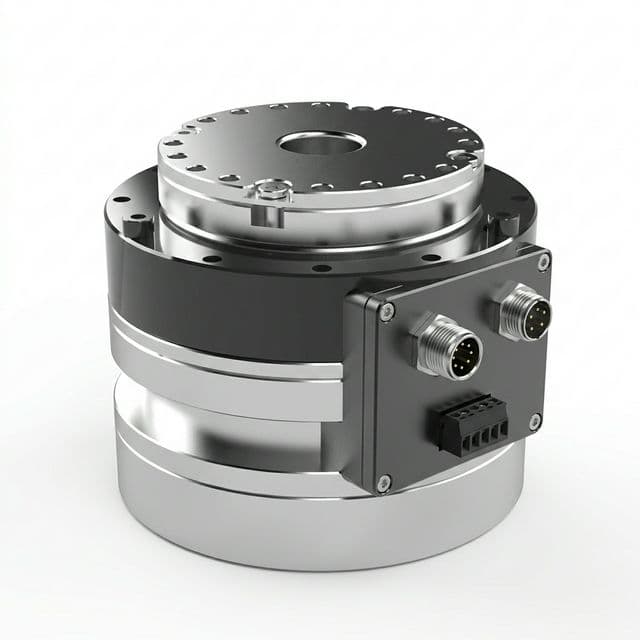
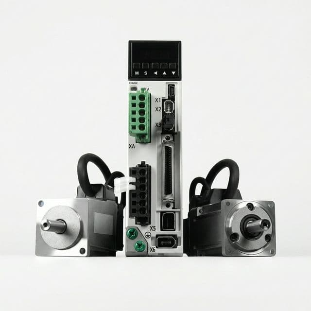
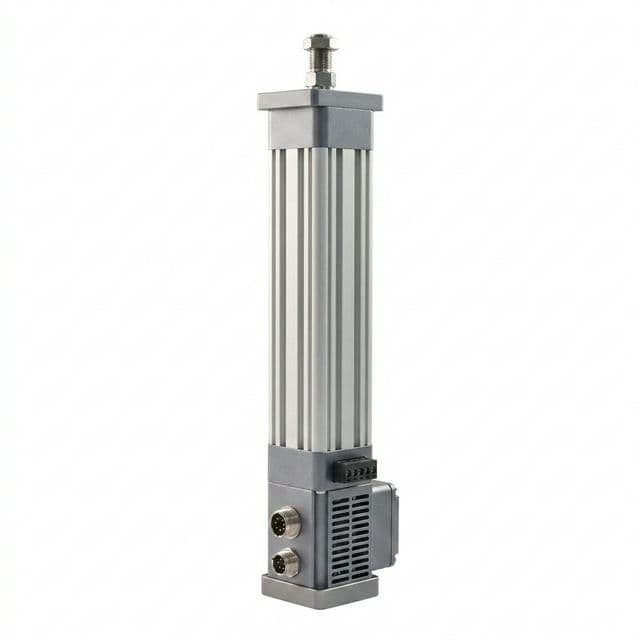
Illustrative components only. Images do not establish torque capacity, compatibility or a match to your calculation; request model-specific documentation.