
AMR Drive Unit Electromagnetic Brake Sourcing Guide: Fail-Safe Holding, Engagement Lag, Incline Sizing, and ISO 3691-4 Compliance
Size an AMR drive unit electromagnetic brake for ramp holding, engagement delay, and emergency-stop energy. Use the RFQ checklist to request supplier evidence.
By Adrian Kowalski · Lead Robotics & Joint Actuator Architect
Last reviewed: 2026/11/01
MDX editorial page reviewed for buyer-facing scope, date boundaries, source traceability, and internal-link coverage.
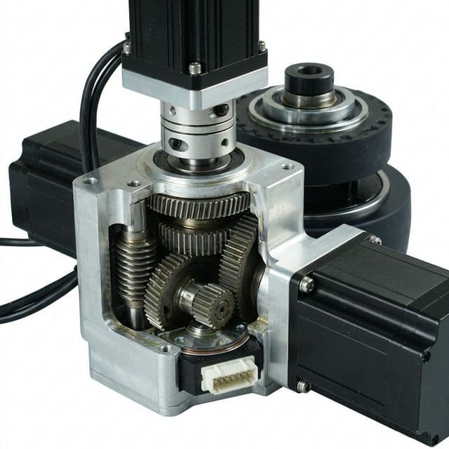
Buyer decision (as of 2026-11-01): Select an AMR drive unit electromagnetic brake against three separate requirements: minimum ramp holding torque, measured engagement delay with the installed suppression circuit, and permitted emergency-stop energy. A parking-only brake is not automatically suitable for stopping a moving vehicle. Accept a flyback diode, varistor, or electronic driver only when the complete stopping chain meets the vehicle's validated distance budget; no circuit topology alone proves ISO 3691-4 compliance.
Reviewed: 2026-11-01. Scope: Global, English-language engineering and procurement guidance for industrial AMR/AGV OEMs, chassis integration engineers, functional safety architects, and sourcing directors. Request an electromagnetic brake sizing and drive unit RFQ review with your payload mass, ramp slope, bus voltage, and emergency stopping requirements.
Scope, Method, and Evidence Boundaries
This guide provides technical criteria for specifying, sizing, and sourcing integrated electromagnetic holding and safety brakes within autonomous mobile robot (AMR) and automated guided vehicle (AGV) traction modules. It applies to differential drive units, dual-steer drive modules, omnidirectional drivetrains, and heavy-payload transaxles.
Methodology:
- Static incline holding analysis using Newton's force balance and gearbox mechanical advantage, without taking credit for gearbox friction.
- Dynamic emergency stop kinetic energy dissipation (E) and thermal absorption limits of friction discs.
- Electrical coil de-energization transient analysis (L/R time constants, back-EMF suppression, and armature engagement delays).
- A preliminary stopping-distance budget to prepare vehicle tests; this is not a standard-prescribed protective-field calculation.
Evidence limits:
- ISO 3691-4:2023 identifies the driverless-truck safety and verification scope. The DIN adoption of IEC 61800-5-2:2016 describes safety-related drive-system integration and validation. DIN VDE 0580 covers electromagnetic-device characteristics, operating conditions, and tests. Public catalogue summaries establish scope, not access to the complete normative clauses. Check the applicable editions and destination-market requirements with the responsible safety assessor.
- Mayr's safety-brake documentation explains spring-applied operation, compatible supply modules, power reduction, and monitoring options. These are manufacturer-specific capabilities, not evidence that this site's drive units include them.
- Numerical examples are reproducible engineering arithmetic derived from explicitly defined vehicle parameters. Actual floor friction (mu), tire compound compliance, ambient temperatures, and supplier manufacturing tolerances must be validated on physical prototype vehicles.
- This guide focuses on industrial logistics in controlled operating zones. Public-road/public-zone use, potentially explosive atmospheres, freezer duty, and hygienic washdown require a separate applicability and environmental review. An enclosure IP rating alone does not qualify a brake for those uses.
Evidence status: No vehicle tests, customer failure statistics, product certification, or measured brake performance are reported here. The worked calculations and diagrams are illustrative engineering analysis. Standards are not automatically statutory in every market, and a compliant component does not establish compliance of the assembled vehicle.
The Core Distinction: Service Braking vs. Fail-Safe Holding
Separate the brake's static holding rating from its dynamic stopping rating. A holding brake may allow only a limited number of emergency stops, or none at the required speed and energy. Obtain both ratings for the exact part number.
Routine stop:      Controlled motor deceleration -> verify low/zero speed -> apply holding brake
Parking:           De-energize brake coil -> springs clamp -> verify stationary hold
Emergency stop:    Execute the validated safety stop sequence
Power loss:        Confirm available braking, engagement delay, and rollback behavior
In BLDC/PMSM traction drives, routine deceleration can use controlled electrical braking, with energy accepted by the battery or dissipated through a suitable resistor. Confirm that the BMS and DC bus can accept regeneration under the worst battery state. Repeatedly applying a parking brake at speed can exceed its permitted friction work and wear budget.
STO removes motor torque; it does not itself apply a mechanical brake or guarantee a stop. A controlled emergency stop and an immediate power-removal stop can have different distances. Assess both where applicable, including loss of the normal deceleration path. Request a dynamically rated brake or another validated braking provision when the holding brake cannot absorb the required emergency-stop energy.
Physical Anatomy: Spring-Applied vs. Permanent Magnet Brakes
Both architectures can provide power-off holding. Selection depends on the exact brake's ratings, mounting, environmental limits, and control circuit rather than payload class alone.
- Spring-applied: Springs clamp a friction rotor when the coil is de-energized. Energizing the coil pulls the armature away and releases the shaft. Several springs do not by themselves establish fault tolerance or a Performance Level.
- Permanent magnet: Permanent magnets provide holding force. A correctly polarized coil counteracts that field to release the shaft. Temperature limits and release-current windows depend on the magnet material and product design.
Engineering & Procurement Comparison Matrix
| Architectural Parameter | Spring-Applied Brake | Permanent Magnet Brake | Sourcing & RFQ Engineering Impact |
|---|---|---|---|
| Power-off holding | Spring force | Permanent-magnet force | Request minimum guaranteed holding torque at specified conditions |
| Release control | Coil overcomes spring preload | Coil counteracts permanent field | Confirm approved voltage/current window and suppression circuit |
| Torque density | Depends on rotor, diameter, and spring arrangement | Can suit compact installations | Compare actual torque and envelope drawings; avoid generic density ratios |
| Temperature limits | Coil, lining, spring, and enclosure dependent | Also constrained by magnet grade | Obtain hot/cold torque and release limits for the exact model |
| Backlash | Hub/spline design may permit play | Some diaphragm designs offer low backlash | Specify allowable shaft play and measure assembled wheel movement |
| Released drag | Depends on clearance and rotor guidance | Depends on armature and release adjustment | Request a measured residual-drag limit; do not assume zero |
| Air-gap maintenance | Wear limits and adjustment depend on model | Adjustment policy depends on model | Obtain inspection method, service limit, and replacement criteria |
| Polarity | Bare coil may be nonpolar; internal electronics may not be | Release field normally requires correct polarity | Follow the supplier wiring diagram for the complete assembly |
| Emergency-stop duty | Must be explicitly rated | Must be explicitly rated | Require energy per stop, permissible speed, repetition, and wear life |
Stopping Distance: A Preliminary Budget for ISO 3691-4 Validation
ISO 3691-4:2023 addresses driverless industrial-truck safety and verification. The model below is an engineering estimate for a stop that relies on the mechanical brake after a delay; it is not a quotation of a normative formula or a protective-field approval.
S_estimate = v × (t_detection + t_control + t_engagement) + v² / (2 × a_net) + S_allowance
Detection -> safety logic / communication -> brake torque builds -> deceleration -> standstill
Record worst-case timing Measure on assembly Validate hold- Detection/control time: Use maximum documented scanner, safety-controller, and communication response times for the configured filters and bus.
- Engagement time: Measure from the safety command to the required braking torque, including the driver, coil decay, armature motion, and torque buildup. Supplier symbols such as t11/t1 can have different definitions; do not substitute a current-decay time for full torque buildup.
- Net deceleration: Use a validated worst-case value for the load, travel direction, slope, floor, and tire condition. Braking torque can exceed available tire traction, so locked wheels do not prove a safe stopping distance.
- Allowance: Include the relevant detection tolerance, geometry, overhang, wear, and operating-zone requirements. No universal 100–200 mm margin is asserted here.
Illustrative level-floor calculation: Assume v = 1.5 m/s, combined detection/control time 0.10 s, engagement time 0.05 s, constant net deceleration 1.0 m/s², and a provisional allowance 0.15 m. Then S_estimate = 0.225 + 1.125 + 0.15 = 1.50 m. If engagement instead takes 0.25 s, the same assumptions give 1.80 m: an extra 0.30 m. These are assumed inputs, not measured brake performance or certified field sizes.
The constant-speed delay term may underestimate downhill acceleration during a power-loss stop. A controlled electrical stop can overlap coil timing; do not double-count that delay. Validate each safety stop mode and power-loss case on the complete vehicle before setting protective fields.
The Freewheeling Diode Trade-off: Coil Demagnetization Delay
A flyback diode protects switching electronics but can prolong coil-current decay. A compatible varistor, TVS, or electronic driver can permit a higher discharge voltage and shorten decay. The complete brake's engagement time also depends on its mechanical state, temperature, air gap, and required torque.
Inductive Energy Release Physics
E_magnetic = 0.5 × L × I², where L is coil inductance and I is coil current before turn-off.
For a simple diode recirculation path, L/R provides an approximate current-decay time scale. It is not a brake engagement-time guarantee. For a roughly constant reverse voltage directly across the coil, a first estimate is t_decay ≈ L × I / V_reverse, neglecting winding resistance. A clamp measured across the switching transistor uses a different voltage reference; do not interchange those voltages.
Distance sensitivity: At a constant 1.6 m/s, an assumed extra delay of 0.25 s adds 0.40 m of travel. This arithmetic explains why the RFQ must specify the installed driver and suppression network alongside the brake, without claiming a universal delay for any topology.
Coil De-energization Circuit Topologies Compared
| Quenching Circuit Topology | Expected Current-Decay Behavior | Electrical Constraint | Stopping-Distance Check | Sourcing & Integration Decision |
|---|---|---|---|---|
| Flyback diode | Low reverse voltage can prolong decay | Confirm coil polarity and switch rating | Measure full engagement time with this diode installed | Accept only if the validated stopping budget is met |
| Diode + Zener | Higher discharge voltage can shorten decay | Check repetitive pulse energy and voltage tolerances | Measure hot/cold torque buildup | Require supplier-approved component values |
| MOV / varistor | Higher clamp voltage can shorten decay | Check clamp tolerance, ageing, and energy rating | Include the actual clamp and wiring in tests | Obtain an approved circuit, not a generic voltage target |
| Electronic brake driver | May provide controlled fast discharge | Check safety manual, diagnostics, and compatibility | Include output switching and brake response | Safety capability depends on the assessed subsystem |
| Unprotected open circuit | Uncontrolled inductive transient | Arcing or semiconductor breakdown can occur | Not a reproducible design basis | Require a defined suppression provision |
| RC snubber | Depends on resistance, capacitance, and circuit | Verify stored energy, ringing, and leakage | Measure rather than infer from topology | Use only with documented brake/driver approval |
A circuit change can affect EMC, insulation stress, diagnostic pulses, and safety certification. Obtain approval from both the brake and output-driver suppliers; do not remove an installed diode solely on the basis of this guide.
Visual Engineering Diagrams
1. Coil Current Decay and Engagement Timing
The diagram illustrates current-decay behavior only. Waveforms are qualitative, with no time scale; the assembled brake's torque response must be measured separately.
Conceptual illustration, not an oscilloscope trace, tested circuit, or installation wiring diagram.
2. Conceptual Spring-Applied Brake Layout
Conceptual layout, not an assembly drawing or a certified product specification. Dimensions, sensor options, release mechanism, and spring arrangement vary by model.
Static Incline Sizing: Mathematical Holding Torque Model
Specify the maximum operating grade, loaded and unloaded configurations, and which braked wheels remain in contact with the floor. Static holding torque and tire-to-floor traction are separate acceptance gates.
The Incline Sizing Formula
For a preliminary equal-sharing calculation, take no credit for gearbox friction:
F_downhill = m_gross × g × sin(alpha)
T_brake,min ≥ k × m_gross × g × sin(alpha) × r / (N × i)
- m_gross: Vehicle tare plus payload, in kg.
- g:
9.81 m/s². - alpha: Ramp angle. For grade G expressed as a decimal,
alpha = atan(G)andsin(alpha) = G / sqrt(1 + G²). - r: Effective loaded wheel radius, in m.
- N: Number of brakes credited with sharing the load equally. Recalculate for uneven sharing, wheel unloading, and required fault cases; a two-brake calculation does not prove one-brake holding.
- i: Motor-to-wheel reduction ratio, e.g.
20for 20:1. - k: Project-selected design reserve. The example uses
k = 2.0; this is not presented as an ISO-mandated factor. Specify minimum torque after allowed wear and at the rated temperatures.
Reverse-efficiency boundary: Backdriving losses reduce torque reaching the motor. Under a moving backdrive definition, T_motor = eta_reverse × T_wheel / i; dividing by reverse efficiency describes a different transmission direction. Static friction is not reliably represented by a running efficiency, so this screening model uses the lossless case and takes no safety credit for friction.
Worked Engineering Example: 1,500 kg Pallet AMR
Assume a gross mass of 1,500 kg, a 6% grade, two equally loaded braked wheels, a loaded wheel radius of 0.100 m, a 20:1 reduction, and design reserve k = 2.0.
| Calculation Step | Reproducible Calculation | Result |
|---|---|---|
| Ramp angle | atan(0.06) | 3.43° |
| Downhill force | 1,500 × 9.81 × sin(atan(0.06)) | 881.3 N |
| Per-wheel tangential force | 881.3 / 2 | 440.7 N |
| Per-wheel holding torque | 440.7 × 0.100 | 44.07 Nm |
| Motor-shaft torque without friction credit | 44.07 / 20 | 2.20 Nm |
| Required minimum torque with chosen reserve | 2.20 × 2.0 | 4.41 Nm per brake |
| One-brake sensitivity, if that case is required | 881.3 × 0.100 / 20 × 2.0 | 8.81 Nm for the remaining brake |
Procurement selection: A guaranteed 4 Nm brake does not meet the illustrative 4.41 Nm equal-sharing target, but that does not prove it will slip under every nominal condition. A 6 Nm candidate clears this static screen only if its guaranteed minimum torque covers temperature, wear, and tolerances. It does not clear the illustrative 8.81 Nm one-brake case.
Also check mu_min × sum(normal load on braked wheels) ≥ F_downhill, with the project's required reserve and actual slope-dependent axle loads. More brake torque cannot compensate for inadequate floor adhesion.
For a review of the assumptions, send the mass, grade, wheel radius, brake count, and reduction ratio with your RFQ.
Thermal Management: Approved Pull-in & Economy Holding
A spring-applied brake normally needs coil power to remain released while the AMR travels. Confirm the rated duty cycle and enclosure temperature rise rather than assuming every coil needs PWM reduction. A continuous-duty coil may be designed for full rated voltage.
For steady DC, P_coil = I² × R = V² / R. For example, an assumed 24 V, 24 ohm coil dissipates 24 W. If its supplier explicitly permits a steady 12 V holding supply after pull-in, the same resistance gives 6 W, a calculated 75% reduction. This is an ideal electrical comparison, not a measured thermal or battery-runtime result.
Supplier-approved pull-in voltage and time -> confirmed release -> approved lower holding current
Safety stop demand -> validated de-energization path -> measured clamp- Pull-in: Follow the exact coil/controller voltage and timing limits. Full rated voltage is ordinary pull-in; applying voltage above the coil's rating is overexcitation and requires explicit approval.
- Economy holding: Request the minimum holding current across bus voltage, winding temperature, air gap, and vibration. Confirm PWM frequency, ripple, and suppression compatibility with the supplier.
- Thermal acceptance: Measure coil/enclosure temperatures under worst ambient and motor load, including low battery voltage. Insulation class alone is not an ambient-temperature or complete-assembly rating.
For PWM, heating follows RMS current and winding resistance. Duty cycle alone does not establish equivalent DC voltage or a 75% power reduction. No universal holding duty cycle, lifespan multiplier, or fleet-runtime improvement is claimed.
Hardware Packaging & Potential Failure Modes
Inspect the mounting interface, service access, and isolation of the dry friction surfaces from gearbox lubricant.
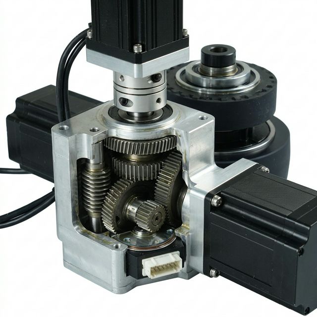
Gearbox and motor-mounting illustration. It does not verify brake location, coil class, ingress rating, or seal material. Request the exact assembly drawing and evidence that lubricant is kept away from dry friction surfaces.
Potential Failure Modes & Supplier Acceptance Gates
These are engineering failure scenarios, not reported customer incidents or measured failure rates.
| Failure Mode | Observable Symptom | Possible Mechanism | Safety / Availability Impact | Sourcing Acceptance Gate |
|---|---|---|---|---|
| Oil contamination | Brake slips or cannot hold the required load | Lubricant reaches dry friction surfaces | Reduced friction torque | Review lubricant isolation, inspection, and replacement policy |
| Hub / spline wear | Increasing rotational play or noise | Reversing loads and inadequate engagement | Torque-path damage or loss | Obtain hub fit, material, wear, and load limits; keep lubricants off friction surfaces |
| Excessive air gap | Slow release, drag, or failure to open | Lining wear or incorrect assembly adjustment | Unexpected immobilization or heating | Obtain model-specific service limits and inspection access |
| Coil overheating / insulation failure | High temperature or electrical fault | Operation outside duty/temperature limits | Loss of reliable release | Check actual coil duty and enclosed temperature rise |
| Excess emergency-stop work | Torque fade, wear, or damaged lining | Energy or repetition exceeds dynamic rating | Degraded subsequent stopping capability | Validate per-stop and cumulative friction work with cooling intervals |
| Manual release left active | Brake does not hold after recovery | Release mechanism remains engaged or is damaged | Unintended rollaway | Define restraint, reset confirmation, and interlock/return behavior |
Safe Brake Control (SBC) & Safe Brake Test (SBT)
A safe brake-control output and a healthy mechanical brake solve different problems. SBC commands an external brake safely; it does not prove that the brake generates the required torque. Required PLr/SIL, architecture, diagnostics, and fault exclusions depend on the applicable safety functions and vehicle assessment, not a blanket “ISO 3691-4 Cat 3 / PL d” label.
Safe Brake Control under IEC 61800-5-2
The DIN adoption of IEC 61800-5-2:2016 covers safety-related drive systems and their integration/validation. Follow the selected brake-controller's safety manual for output wiring, fault detection, supply limits, and compatible suppression. A monitored high-side/low-side arrangement is one possible implementation; it is not a universal circuit prescription.
Safety demand -> assessed brake-control output -> approved coil / suppression -> mechanical brake
                         diagnostics                engagement time             holding torque
Diagnostic test pulses must remain within the brake/controller limits so they neither release a clamped brake nor unintentionally apply a released brake. Feedback indicating armature position does not prove holding torque or automatically detect wear.
Brake Test Commissioning Routine
SBT is a supplier/system brake-test function; do not assume that every drive implements it or that it is a universally mandated standardized sub-function. Agree a protected test procedure with the safety assessor and component suppliers:
- Conditions: Secure the vehicle against unintended travel, define load/slope and safe personnel access, and confirm the test will not exceed brake or transmission ratings.
- Method: Apply the brake and use a calibrated, limited test torque or another approved load method. Establish where torque is measured and account for gearbox backlash and encoder resolution.
- Acceptance: Set torque, duration, movement tolerance, test interval, and failure response from the design assessment and supplier limits. Record results; no universal 24-hour interval, 150% motor torque, or 2–5° movement threshold is asserted.
Use the AMR functional safety sourcing guide to structure the wider supplier handoff. This article supplies a brake-specific RFQ framework, not a certification decision.
Engineering & Procurement RFQ Checklist
Require written evidence for the exact brake, drive unit, and controller combination before freezing the specification. Treat missing data as an open acceptance gate, not an assumed pass.
Gate 1: Static Holding Torque & Incline Reserve
- Record gross/tare mass, maximum grade, wheel radius, ratio, braked-wheel loads, and load sharing.
- Agree the design reserve and required fault cases; specify minimum hot/cold/worn holding torque.
- Confirm the torque reference shaft and demonstrate tire adhesion as well as brake holding.
Gate 2: Electrical Suppression & Engagement Delay
- Obtain the coil, driver, and suppression part numbers and supplier-approved wiring diagram.
- Define time from safety command to required braking torque; include voltage, temperature, wear, and tolerances.
- Measure the installed stopping chain for each relevant stop mode and power-loss case.
Gate 3: Thermal Management & Economy Holding
- Obtain coil duty rating, insulation limits, permissible winding temperature, and enclosure test conditions.
- Use only approved pull-in/overexcitation and reduced-current holding settings.
- Request measured temperature rise with the motor operating in the final sealed enclosure.
Gate 4: Dynamic Emergency-Stop Energy
- Estimate total energy:
E = 0.5 × m × v² + sum(0.5 × J × omega²) + m × g × h_drop, adding downhill potential-energy release where relevant. - Allocate energy to each brake using the actual stop sequence; distinguish translational mass from rotating inertias and avoid double-counting equivalent inertia.
- Verify per-stop energy, speed, repetition/cooling interval, total friction work, and wear life against supplier limits with an agreed reserve. Do not assume equal sharing or 10,000 permitted stops.
Gate 5: Diagnostics & Manual Release
- Define what each feedback signal proves: released position, applied position, wear, or measured torque.
- Specify a safe recovery/towing procedure, restraint on slopes, manual-release access, and reset/interlock behavior if fitted.
- Obtain the required brake-test procedure, interval, records, and fault response.
Gate 6: Environmental Sealing & Contamination
- Verify separation of gearbox lubricant from dry friction surfaces; obtain the seal arrangement and material compatibility.
- Specify ingress, temperature, condensation, dust, and cleaning conditions for the complete assembly.
- Obtain lining wear/replacement limits, air-gap service limits, inspection access, and maintenance instructions.
Sourcing & RFQ Parameter Specification Matrix
| RFQ Engineering Parameter | Unit / Evidence | Sourcing Target | Design Check | Under-Specification Risk |
|---|---|---|---|---|
| Static holding torque | Nm, minimum guaranteed | Meets load cases and agreed reserve | State reference shaft, wear, and temperature | Ramp rollback |
| Engagement delay | ms, torque buildup trace | Meets allocated stopping-distance budget | Use installed driver and suppression | Protective-field overshoot |
| Coil supply / holding control | V, A, duty, approved wiring | Within exact model/controller limits | Verify low bus voltage and hot winding | Drag, loss of release, or overheating |
| Working air gap | mm, inspection instructions | Supplier nominal and wear limit | Define access and maintenance interval | Failure to release |
| Emergency-stop work | J/stop, J/hour, lifetime work | Within dynamic rating and agreed reserve | Include slope energy and load sharing | Fade or premature wear |
| Manual recovery | Procedure and release drawing | Safe restraint and deliberate reset | Review towing on slopes | Uncontrolled rollaway |
| State / torque diagnostics | Signal definition and test record | Meets the assessed safety function | Position feedback alone is insufficient | Undetected brake degradation |
| Lubricant isolation | Drawing and compatibility evidence | Protects dry friction surfaces | Review seal failure path and inspection | Loss of friction torque |
Frequently Asked Questions (FAQ)
Q1: Can an electromagnetic holding brake perform routine deceleration?
Only if the exact model is rated for that duty. A parking brake's static torque rating does not establish permitted dynamic energy, speed, or repetition. Use controlled motor deceleration for routine stops where designed, then apply the holding brake at the supplier-approved speed. Verify the separate emergency-stop case.
Q2: Must every AMR brake use a varistor instead of a flyback diode?
No. A diode can prolong coil-current decay, while a compatible higher-voltage clamp can shorten it. Accept the complete brake/driver/suppression combination only after checking voltage stress, diagnostics, EMC, and measured engagement time against the stopping-distance budget.
Q3: When should an OEM compare permanent magnet and spring-applied brakes?
When packaging, released drag, backlash, temperature, or control requirements are decisive. Compare actual guaranteed torque, release-current limits, thermal ratings, and dynamic duty. Neither payload class nor the presence of several springs establishes safety integrity.
Q4: How can we reduce coil heating in a sealed drive unit?
Ask whether the supplier approves reduced-current holding after pull-in. Use its controller settings and measure the final enclosure temperature. PWM duty cycle alone does not establish RMS coil current or heating, and a low holding voltage that works cold may fail at a hot winding or low battery voltage.
Q5: Is a spring-return manual release mandatory for every warehouse AMR?
This guide does not establish a universal mandate. Define a safe recovery method for the vehicle, including immobilization before release, slope restraint, access, towing limits, and restoration of braking. If a manual release is fitted, assess spring return or monitored reset as part of that procedure.
Q6: Does Safe Brake Control establish ISO 3691-4 compliance?
No. SBC addresses the brake-control output within its declared safety limits. Mechanical holding torque, dynamic duty, tire traction, diagnostics, vehicle stopping behavior, and integration still need validation. A component certificate does not certify the complete AMR.
Q7: Should reverse gearbox efficiency reduce the specified holding torque?
Do not take credit for friction in this preliminary safety screen. With a moving backdrive definition, torque reaching the motor is multiplied by reverse efficiency; static holding friction is a different condition. Use the lossless ratio, an agreed reserve, and actual holding tests across temperature and wear.
Q8: Does a brake microswitch automatically detect air-gap wear?
Not necessarily. A switch may report only armature position. Require the supplier to define what the signal detects, its adjustment and tolerances, and whether a separate wear monitor or direct measurement is needed. Use the exact model's inspection and replacement limits rather than a generic air-gap value.
Sources and Reference Standards
Reference review: 2026-11-01. These public publisher/manufacturer pages establish document scope and available brake-control concepts. Full standards, exact clause interpretation, product manuals, and destination-market obligations require separate confirmation; none of the sources certifies the worked examples or this site's products.
- ISO 3691-4:2023 — Industrial trucks — Safety requirements and verification — Part 4: Driverless industrial trucks and their systems. Official scope reference for AMRs/AGVs and controlled operating zones. The catalogue lists a revision in development; confirm the applicable edition before design freeze.
- DIN EN 61800-5-2:2017-11, adopting IEC 61800-5-2:2016 — Safety requirements — Functional. DIN Media's publisher summary describes safety-related drive-system design, integration, and validation; it does not specify one universal AMR brake-output circuit.
- DIN VDE 0580:2011-11 — Electromagnetic devices and components — General specifications. Publisher overview covers device characteristics, operating/environmental conditions, safety requirements, and tests. Use the exact brake manual to set temperature and air-gap limits.
- Mayr safety brakes and supply/monitoring modules — Manufacturer technical overview. Supports the explanation of de-energized spring application, compatible power-reduction modules, and monitoring options. Manufacturer claims apply to its specified products; request the selected model's manual and data.
Next Steps for OEM Engineering & Sourcing Teams
Before comparing quotations, agree the minimum holding torque, engagement-time budget, dynamic emergency-stop duty, and acceptance evidence for the complete drive assembly.
- Drive architecture: Review custom AGV and AMR drive integration and AGV drive-steer integration to define the packaging and load cases. Confirm brake options for the quoted model rather than assuming Class H coils, a particular seal material, or SBC capability.
- Heavy-payload sourcing: Review heavy payload drive units, then request the exact brake torque, energy, environmental, and control data for your configuration.
- Engineering RFQ: Submit your gross/tare mass, ramp grade, wheel radius, ratio, bus voltage, speed, and stopping-distance target. Include your CAD envelope and required fault cases so the application team can review sizing assumptions and identify the supplier evidence still needed before approval.