
Differential Drive vs. Steer-Drive Units: OEM Sourcing Guide for AMR & AGV Kinematics
Compare differential and steer-drive units for AMR/AGV sourcing. Check kinematics, wheel loads, braking, five-year cost assumptions, and your RFQ checklist.
By Adrian Kowalski · OEM Sourcing Editorial Contributor
Last reviewed: 2026/10/25
MDX editorial page reviewed for buyer-facing scope, date boundaries, source traceability, and internal-link coverage.

Buyer decision: For AMR drive unit sourcing, shortlist differential drive when a compact chassis and in-place turning suit the route. Shortlist steer-drive when wheel heading control or coordinated lateral docking is required. Payload alone does not determine the architecture: there is no universal 1,000kg or 1,200kg changeover point. Compare loaded wheel forces, packaging, turning duty, stopping tests, and lifecycle costs before requesting samples.
Reviewed: 2026-10-25. Scope: Global, English-language guidance for industrial AMR/AGV OEMs, systems engineers, and procurement teams. If you already have a route layout, request an architecture and RFQ review with your chassis envelope and loaded wheel reactions.
Scope, Method, and Limits
This guide compares two independently driven, coaxial fixed wheels with passive supports against actively steered traction modules. A four-wheel skid-steer chassis has different contact constraints and must not be treated as the same differential-drive model. Single-steer, dual-steer, and four-steer layouts also have different motion capabilities.
Method: Use ideal no-slip kinematics to establish possible motions, then apply the comparison matrix and RFQ gates to the actual vehicle. The ros2_control kinematics documentation supplies the motion-model reference. VDI 2510 provides AGVS system context; its public abstract is not evidence for a load or wear threshold.
Evidence limits: This is an engineering selection framework, not a measured supplier comparison. No auditable fleet reliability dataset or controlled tire-life test accompanies this article. All TCO numbers below are explicitly hypothetical budgeting inputs, not quotations or observed savings. Product images show packaging only; they do not verify load rating, steering configuration, or safety performance.
The baseline is industrial operation on a defined floor and route. Outdoor surfaces, public roads, freezer or explosive environments, towing, and elevated loads need additional assessment. Define total vehicle mass separately from payload, center of gravity, wheel-load distribution, floor condition, gradients, speed, and duty cycle. Final acceptance belongs to the OEM/integrator and the project safety assessment.
Architectural Fundamentals: Kinematics and Mechanical Anatomy
1. Differential Drive Units (Two Fixed Drive Wheels)
Two independently controlled wheels on a common transverse axle produce forward speed and yaw. With wheel-ground speeds v_R and v_L, and wheel track W in metres:
forward speed v = (v_R + v_L) / 2
yaw rate omega = (v_R - v_L) / W
v_R = v + omega * W / 2
v_L = v - omega * W / 2
These are ideal kinematic relationships, consistent with the ros2_control reference. Opposite wheel speeds allow rotation about the axle midpoint, which need not be the chassis geometric center. The complete chassis, load overhang, and casters still sweep an area. A differential vehicle cannot command instantaneous sideways translation.
Packaging can be compact, and the architecture avoids a separate active steering axis. Verify the actual CAD envelope, suspension travel, caster swing, brake clearance, and cable exits rather than assuming a universal height limit.
2. Steer-Drive Units (Active Steered Traction Wheels)
A steer-drive module combines traction with controlled wheel orientation. A single front steered wheel and two fixed rear wheels form a tricycle layout with a finite turning envelope. Coordinated multiple steer modules can support sideways travel and in-place rotation only if every supporting wheel, steering range, and chassis constraint permits that motion. Steering reorientation takes time; lateral capability does not imply instantaneous direction changes.
For a simple bicycle/tricycle model, tan(delta) = L / R, where L is wheelbase and R is the rear-axle-midpoint turning radius. This formula does not specify arbitrary multi-steer layouts. Such layouts need module-specific speed and angle commands.
Check the supplier's steering torque, allowable wheel loads, backlash, position feedback, cable rotation limits, and maintenance access. Neither a tall steering column nor an endless-rotation slip ring is intrinsic to all steer-drive units.
Technical Comparison Matrix: Differential vs. Steer-Drive
| Evaluation Dimension | Differential Drive Unit | Steer-Drive Unit | Engineering & Sourcing Impact |
|---|---|---|---|
| Motion inputs | Two wheel speeds control forward motion and yaw | Traction speed plus steering angle for each active module | Confirm the controller model matches the complete wheel layout. |
| Turning envelope | Can pivot about the drive-axle midpoint | Single-steer follows a curve; compatible multi-steer layouts can pivot | Compare the swept chassis and load, not only wheel turning radius. |
| Sideways docking | Cannot translate directly sideways | Possible with a compatible coordinated multi-steer layout | Ask for a loaded lateral-docking demonstration, including passive wheels. |
| Tire contact | Ideal two-wheel geometry permits rolling; finite contact patches and caster swivel can add losses | Aligned wheels can roll; stationary steering or alignment errors can still scrub | Test the actual tire compound, floor, load, and turning duty. |
| Payload and wheel loads | Limited by the selected modules and chassis load distribution | Also limited by module, bearing, steering, and chassis ratings | There is no architecture-wide payload cutoff; obtain rated and peak wheel-load data. |
| Packaging | Often compact; caster clearance still matters | Envelope varies with vertical or horizontal packaging | Compare CAD at full suspension travel and steering range. |
| Odometry | Wheel radius, track calibration, and slip affect estimated pose | Steering-angle error, wheel radius, and slip affect estimated pose | Both need localization validation under the real duty cycle. |
| Controls | Coordinate two traction channels | Coordinate steering position and traction channels | Select fieldbus timing from required response and controller evidence. |
| Braking and faults | Unequal braking forces can cause yaw | Steering faults, unequal grip, and load transfer can alter trajectory | Neither architecture guarantees a safe stopping path without vehicle tests. |
| Lifecycle cost | Fewer active steering components; tire and caster costs are duty-dependent | Additional steering hardware and service items; wear remains duty-dependent | Compare complete installed systems using matched assumptions and service quotes. |
The Physics of Floor Contact: What to Validate
A two-wheel differential pivot does not inherently require the gross lateral sliding of a four-wheel skid-steer chassis. In the ideal point-contact model, each drive wheel rolls along its own circular path. Real tires deform over a finite contact patch, and caster alignment, wheel spacing, floor roughness, and rapid reversals can add resistance and wear. Steered wheels can also scrub while turning under load at rest or when their commanded angles disagree.
For a first traction screen, available longitudinal force <= mu * N_driven, where N_driven is the normal force on the driven wheels in newtons. This simplified friction bound is not a tire-wear model; turning and simultaneous braking share the contact-force capacity. Measure friction and loaded wheel reactions for the project rather than applying a generic coefficient.
Illustrative load calculation: A 1,600kg loaded vehicle has about 1,600 * 9.81 = 15,696 N of total static weight. If an assumed 60% rests on two equally loaded drive wheels, each carries 15,696 * 0.60 / 2 = 4,709 N, approximately 480kg mass-equivalent. That is not 800kg per drive wheel. Ramp load transfer, offset payloads, acceleration, and suspension can invalidate the equal-load assumption. This arithmetic selects questions for the supplier; it does not approve either architecture.
For samples, record wheel load, tire specification, floor condition, speed, turn radius, pivots per hour, ambient temperature, and test duration. Measure wear, drive current, tire temperature at defined locations, and any floor marking. Acceptance limits must come from the selected tire/module documentation and agreed tests. This guide supplies no universal delamination temperature or tire-life improvement percentage.
Visual Kinematic and Vector Comparison
The diagram separates a differential pivot from a single-steered-wheel turn. It is a conceptual illustration, not a measured force map or a safety-field design. On small screens, scroll horizontally to read its labels.
Hardware Packaging Examples and Evidence Limits
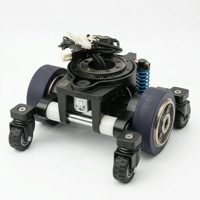
Figure 1: Packaging example from the site product library. The visible assembly includes two large wheels, auxiliary casters, and a top ring gear. Confirm each axis and load rating in its drawing; the image does not establish a pure fixed-axis differential architecture.
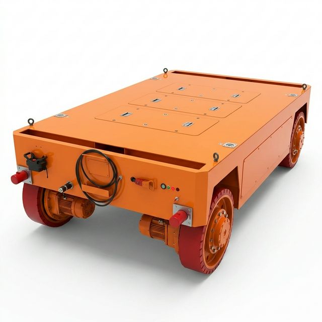
Figure 2: Transport-platform packaging example from the site product library. A filename or photograph is not verification of payload capacity, hidden steering mechanisms, tire life, or floor compatibility. Obtain the configuration drawing and test report.
Application Boundaries: When to Shortlist Each Architecture
Where Differential Drive is a Useful Starting Point
- Low-profile under-ride AMRs: Compare compact differential modules against the available CAD envelope, lift mechanism, and battery space. Height alone does not exclude all steer-drive designs.
- Routes that need frequent in-place turns: Verify chassis/load sweep, caster alignment, traction, and floor wear using the expected turning cycle.
- Programs with a simple motion requirement: If direct lateral docking is unnecessary, avoiding steering axes can reduce component count. Price the complete system before claiming a cost advantage.
Where Steer-Drive Deserves Evaluation
- Forklift-style or constrained curved-path layouts: Select the steering geometry around wheelbase, load stability, required aisle maneuvers, and docking tolerance. Steering does not guarantee a positioning accuracy.
- Lateral or diagonal docking: Specify coordinated multi-steer motion and compatible support wheels; a single steered wheel with fixed rear wheels cannot crab.
- Heavy transfer platforms or towing: Compare wheel loads, drawbar demand, steering torque, articulation, and trailer sweep. Heavy mass alone does not prohibit differential drive, and steer-drive does not eliminate jackknife risk.
- Outdoor or faster routes: Validate grip, stability, grade, environmental protection, and stopping performance at the specified speed. There is no universal 2.5m/s architecture boundary in this guide.
Functional Safety and Dynamic Braking: Procurement Boundaries
ISO 3691-4:2023 covers safety requirements and verification for driverless industrial trucks and their systems. Its public catalogue establishes that scope, not the detailed requirements of an unseen clause. It does not establish that steer-drive is mandatory above a payload threshold. Confirm the applicable edition and destination-market requirements with the project safety lead before design freeze.
For both architectures, request vehicle-level evidence:
- Define stopping tests for the intended mass range, speed, direction, gradient, floor conditions, and turning states. Include sensing/control response time and the swept vehicle and load in the protective-field assessment.
- Assess asymmetric traction/braking, loss of steering feedback, uncontrolled traction commands, loss of communications, and power loss. Unequal left/right brake forces can generate a yaw moment of magnitude
abs(F_L - F_R) * W / 2; this identifies a test case, not a prediction of a spin. - Assign required safety functions, performance levels, and architectures through the applicable standard and risk assessment. Do not infer one universal control category from the drive topology.
- Separate motor torque removal, controlled deceleration, parking/holding brakes, and regenerative energy handling. Safe Torque Off (STO) does not itself provide stopping torque or hold a vehicle on a slope. A parking brake needs a suitable dynamic-stop rating before being used that way.
- Validate protective fields for every permitted motion, including differential pivots, steered curves, and any lateral travel. Holding a steering angle does not guarantee a straight or repeatable stop on unequal grip.
Outdoor/public-road, severe-environment, and towed-trailer hazards need separate scope review; the ISO public abstract identifies exclusions and limits. A component certificate alone does not approve the complete vehicle.
Control and Electrical Integration Complexity
For differential drive, map the host's forward/yaw command to the two wheel speeds and validate wheel radius, track, acceleration limits, feedback direction, timeouts, and odometry. Fleet coordination interfaces and motor-control loops have different responsibilities; a fleet message does not replace a wheel controller.
For steer-drive, coordinate each module's angle and traction speed. Agree steering travel, reversal behavior, alignment before traction, and behavior at zero commanded speed. If cable rotation is limited, implement travel limits and recovery; unlimited rotation needs a suitable mechanical/electrical design.
Absolute single-turn feedback may be sufficient when orientation within one revolution is the only required state. Multi-turn tracking or another reference may be needed for cable-wrap management. Incremental feedback can use a controlled, assessed homing procedure; it is not inherently a defective design. Verify reboot and recovery behavior on the actual vehicle.
Neither architecture universally requires EtherCAT, a 1–2ms bus cycle, or a particular commissioning duration. Obtain the controller interface description, supported modes, timing budget, feedback resolution, fault reactions, and an integration demonstration for the proposed system.
Five-Year Total Cost of Ownership: A Reproducible Example
Hypothetical budget scenario, USD, 50 vehicles over five years. The following numbers are chosen to demonstrate arithmetic; they are not supplier quotations, tire-life measurements, or field downtime records. Assume constant annual operating costs, no discounting, and identical production demand. Both proposals must cover the same vehicle-level scope.
| Cost Input | Differential Fleet | Coordinated Steer-Drive Fleet |
|---|---|---|
| Initial installed drivetrain cost per vehicle | $2,200 | $5,800 |
| Initial drivetrain cost for 50 vehicles | $110,000 | $290,000 |
| Assumed annual tires/casters/service, fleet | $45,000 | $9,000 |
| Assumed annual floor maintenance allocation, fleet | $7,000 | $1,000 |
| Assumed annual drive-related downtime cost, fleet | $45,000 | $6,000 |
| Annual recurring subtotal | $97,000 | $16,000 |
| Five-year modeled total | $595,000 | $370,000 |
Calculation: five-year total = initial fleet cost + 5 * annual recurring subtotal. Under these assumptions, the steer-drive premium is $180,000, assumed annual recurring savings are $81,000, and simple payback is 180,000 / 81,000 = 2.22 years, about 27 months. Those savings result from the inputs, not from kinematics alone.
Sensitivity: If annual recurring savings are only $30,000, payback becomes six years, outside this horizon. At zero or negative savings, there is no positive operating-cost payback. Obtain service quotations and pilot records before relying on either result. Add integration engineering, energy, financing, spares stock, and replacement modules where they differ; they are excluded from this example. Attribute downtime to verified drivetrain causes to avoid charging localization or route faults to the wrong architecture.
OEM Sourcing and RFQ Engineering Checklist
Use this checklist to compare proposals on equal terms. If a requirement is unresolved, keep the sample decision open. Request a sourcing review with the missing items identified rather than treating a checklist score as approval.
| Sourcing Gate | Responsible Team | Requirement to Define | Supplier Evidence / Acceptance Method |
|---|---|---|---|
| Motion and route fit | Systems engineering | Forward, reverse, pivot, lateral docking, aisle and load sweep | Loaded route demonstration and wheel-layout drawing. |
| Packaging | Mechanical | Actual mounting envelope, suspension travel, caster swing, service access | Configuration-specific STEP model and installation drawing. |
| Loads and traction | Mechanical | Total mass versus payload, wheel reactions, gradient, acceleration, drawbar demand | Rated/peak wheel-load limits and a calculation with agreed assumptions. |
| Tire and floor duty | Materials / operations | Tire compound, surface, turn frequency, ambient temperature, wear limits | Representative loaded duty test with temperature and wear records. |
| Steering and feedback | Controls | Steering torque, backlash, usable range, boot reference, cable limits | Encoder/gearbox data and power-cycle/fault-recovery demonstration. |
| Electrical interface | Electrical / software | Supply range, peak current duration, protocol, command timing, regen handling | Interface document, timing trace, and energy-handling design review. |
| Stopping and faults | Safety lead / integrator | Required functions, stopping envelope, gradients, fault cases | Component safety documentation plus complete-vehicle validation records. |
| Service and commercial scope | Procurement / operations | Identical bill-of-material scope, wear-part prices, warranty exclusions, lead times | Itemized quote, spares list, and documented regional support commitments. |
Frequently Asked Questions (FAQ)
Can a differential drive AMR move directly sideways?
No. Two fixed coaxial drive wheels provide forward motion and yaw, not instantaneous lateral translation. Coordinated steer modules can enable lateral docking when the complete wheel layout and steering range permit it; a single steered wheel with fixed rear wheels cannot.
Is steer-drive mandatory above 1,200kg payload?
No universal threshold is established here. Payload differs from total vehicle mass and individual wheel load. Select against the actual module ratings, support geometry, traction, turning duty, and validated stopping behavior. A heavy differential design is not automatically unsuitable, and a high-rated steered module does not approve the whole chassis.
Why can tires wear or delaminate during repeated turns?
Contact deformation, compound selection, temperature, wheel load, bonding quality, floor conditions, and duty all matter. Differential caster swivel and stationary steering can each add contact stress. Diagnose using tire-supplier limits and representative tests; this article provides no universal failure temperature or replacement interval.
Does a steer-drive unit need homing at every power-up?
It depends on feedback and mechanical design. Absolute orientation feedback can avoid a movement-based reference search; incremental feedback may require a controlled reference procedure. Single-turn angle and multi-turn cable position are different requirements. Verify safe reboot behavior rather than specifying multi-turn feedback for every application.
How does floor unevenness affect the two architectures?
Both depend on adequate wheel contact and load distribution. Unevenness can unload a driven wheel, reduce braking or traction capacity, and disturb odometry. Assess suspension/compliance, chassis stiffness, wheel reactions, and the actual floor profile. A steered wheel does not preserve traction simply by holding an angle.
Can we retrofit steer-drive into an existing differential chassis?
Possibly, after reviewing module clearance, load paths, steering range, wiring, controller support, and the complete safety concept. Request a CAD/interface study and repeat affected vehicle tests. There is no universal height or software-rewrite requirement applicable to every retrofit.
Does regenerative braking make either layout safer?
Regeneration is a controller and energy-system capability, not an inherent safety guarantee of the wheel layout. Verify battery charge acceptance, DC-bus overvoltage protection, any braking resistor, torque coordination, and fallback when regeneration is unavailable. Validate stopping and slope holding separately.
Strategic Sourcing Next Steps
- Compare the motion and RFQ requirements in our AGV drive unit engineering guide.
- For steering options, review AGV drive-steer units and compare configuration-specific ratings in heavy payload drive units.
- For packaging or controller integration, review custom drive assemblies and custom drive system design.
Send an architecture and RFQ inquiry with your chassis CAD envelope, total mass and payload, wheel-load estimate, floor/gradient, target motions, speed, and duty cycle. Ask for a configuration-specific drawing, rated limits, interface details, itemized quote, and proposed sample-validation plan.
Sources and Verification Boundaries
Public pages checked on 2026-10-25. Standards catalogue pages establish document identity and scope; they do not substitute for access to the normative text. The ros2_control Rolling page is development documentation. Recheck the applicable standard edition and supplier documentation before design freeze.
| Source | Verifiable Contribution | Limits of This Citation |
|---|---|---|
| ISO 3691-4:2023 catalogue | Identifies the safety and verification standard for driverless industrial trucks, including AMR/AGV examples and operating-zone scope. | Public abstract only; no clause-level interpretation, architecture mandate, tire-life data, or compliance approval is claimed. |
| VDI 2510 — Automated Guided Vehicle Systems | Publisher page dated 2005-10, providing AGVS terminology and in-house material-flow context. | The public abstract does not establish payload cutoffs, tire-wear percentages, or current product ratings. |
| ros2_control — Wheeled Mobile Robot Kinematics | Documents differential, car-like, Ackermann, and multi-module swerve motion models and their assumptions. | Ideal kinematics do not predict tire life, stopping safety, or actual localization accuracy. |