
AMR Drive Unit Suspension & Compliant Floating Sourcing Guide: Ground Contact, Spring Preload, and Traction Stability
Compare AMR drive unit suspension options, calculate spring preload and travel, and check traction and scanner clearance. Send floor and load data for an RFQ.
By Adrian Kowalski · B2B Applications & OEM Program Lead
Last reviewed: 2026/10/28
MDX editorial page reviewed for buyer-facing scope, date boundaries, source traceability, and internal-link coverage.
Buyer decision (as of 2026-10-28): Choose AMR drive unit suspension by the minimum driven-wheel normal force, measured floor profile, usable compression/rebound travel, and braking pitch of the complete chassis. A floating drive unit can help multi-wheel platforms retain contact, but no universal stroke, preload percentage, or speed threshold guarantees traction. Compare supplier force-versus-travel data before approving an architecture.
Reviewed: 2026-10-28. Scope: Global, English-language engineering and procurement guidance for industrial AMR/AGV OEMs, chassis designers, and sourcing teams. Request a suspension sizing and RFQ review with your vehicle masses, support geometry, and floor measurements.
Scope, Method, and Evidence Boundaries
This guide compares mechanical suspension and floating linkages in industrial AMR traction units. It covers drive-wheel contact, support-caster load sharing, spring sizing, and supplier acceptance evidence.
Method: Use a static wheel-load model, a friction-limited traction calculation, a spring force-versus-travel check, and a scanner-clearance calculation. The worked example below is reproducible arithmetic using explicitly assumed inputs, not a tested robot or a customer case study.
Evidence limits:
- Standards provide measurement or safety context. ASTM E1155-20 is a floor measurement reference; ISO 3691-4:2023 concerns driverless truck safety and verification; VDI 2510 provides AGVS context. None of these catalogue references establishes the numerical spring ratings of a drive unit.
- The simplified equations assume direct vertical spring action and, where stated, equal traction sharing. Linkage ratios, guide friction, tire deflection, unsprung weight, and transient loads require additional modelling and physical tests.
- Friction depends on the tire, surface, contamination, temperature, and wear. Measure a conservative value for the actual operating conditions rather than assuming one from a floor material name.
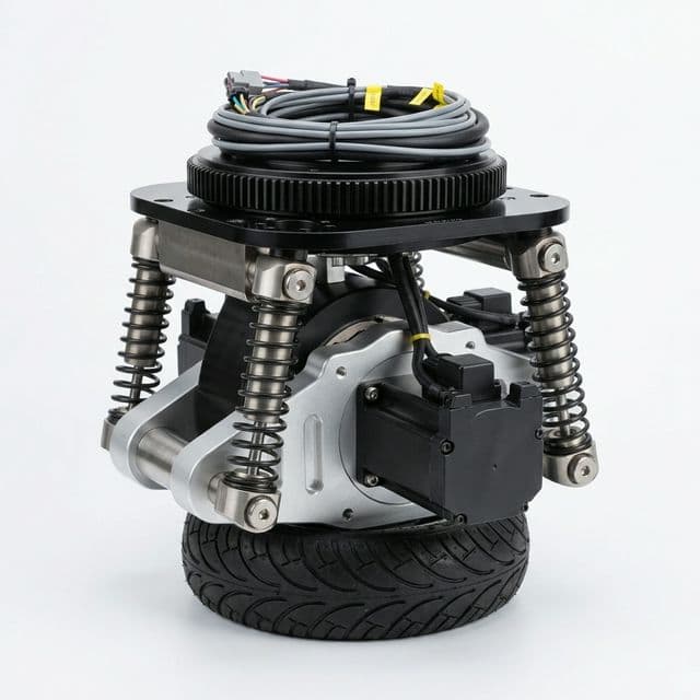
- The cover photo illustrates visible hardware packaging. It does not establish wheel compound, rated load, damping, travel, or fatigue life.
- This is indoor sourcing guidance, not a safety certification. Freezer, washdown, outdoor, and ramp operation need additional environmental and vehicle-level assessment. Select the contractual standards edition and local requirements for each project.
The Root Cause of Field Traction Loss & Odometry Drift
A drive unit can have enough motor torque yet fail to propel a robot when a driven wheel becomes lightly loaded. In a rigid chassis with more than three contact points, floor shape and the stiffness of the tires, frame, and caster mounts affect how the support reactions are shared. Static equilibrium alone generally cannot determine every wheel load.
If support casters ride over high points while a central drive wheel crosses a depression, the drive wheel may unload or lose contact. The friction-limited boundary is:
F_traction_max = mu × F_NHere F_N is the normal force on the driven wheel and mu is the applicable friction coefficient. At a fixed coefficient, a 70% reduction in normal force reduces the friction-limited traction capacity by 70%. Wheel slip occurs only if the requested force exceeds the available capacity; it is not an automatic consequence of every floor dip.
Slip can make encoder-based travel estimates disagree with actual movement. The resulting localization error depends on sensor fusion and slip detection. Repeated slipping can also accelerate tire wear. Suspension is one part of the remedy alongside tire selection, torque limiting, floor maintenance, and navigation robustness.
Rigid mounting remains an option where the support geometry, tire or caster compliance, floor envelope, and required traction have been verified. A cleanroom label or a payload category alone cannot approve or reject it.
Industrial Floor Realities: DIN 18202 & ASTM E1155
Construction flatness specifications and robot suspension travel describe different things. For projects referencing DIN 18202, obtain the contracted edition, table/line, measurement spacing, and actual floor survey. A straightedge flatness deviation is not a permissible joint step or a direct suspension-stroke requirement.
ASTM E1155 uses floor flatness and levelness numbers (F_F and F_L). These statistical measures do not directly specify the worst local dip beneath one driven wheel. A defined wheel path, a dock transition, and an expansion joint need measurements along the intended vehicle route. Do not convert an F_F/F_L pair into a universal ±mm suspension requirement.
Floor Profile vs. Suspension Evidence Matrix
Use this matrix to request measurements and acceptance evidence. It is an RFQ decision aid, not a table of mandatory standard limits. Derive usable compression and rebound travel from vehicle geometry, wheel loads, floor extremes, tolerances, and wear allowances.
| Deployment condition | Measure or obtain | Suspension decision | Risk to investigate | Supplier acceptance evidence |
|---|---|---|---|---|
| Floor specified to DIN 18202 | Contracted table/line, gauge spacing, route profile | Model relative wheel displacement rather than copying a flatness number | A compliant floor can still contain a difficult local transition | Motion study using surveyed elevations and chassis geometry |
| Floor reported using ASTM E1155 | F_F/F_L report plus local route measurements | Calculate rebound/compression needs from local geometry | Statistical averages can conceal a problematic wheel path | Joint and depression traversal tests with wheel-load logging |
| Expansion joints and trench plates | Step height, gap width, edge shape, crossing angle | Check tire deformation, available travel, and end-stop energy | Wheel impact, loss of contact, and peak bearing load | Loaded and tare crossing tests at agreed speeds |
| Cold storage | Temperature range, frost profile, condensation, friction | Check spring, seal, damper, and lubricant behaviour at temperature | Stiction, reduced friction, or temperature-dependent force | Cold-soak force/travel and vehicle traction results |
| Ramps and dock plates | Grade, crest geometry, lip, break-over clearance | Include grade force and support-contact changes | High-centering, wheel unloading, or inadequate braking | Route-specific ramp traversal and stopping evidence |
| Mezzanine and steel decking | Deflection under load and vibration spectrum | Assess coupled floor/chassis dynamics | Cyclic unloading or sensor vibration | Vehicle/deck response measurements under representative load |
| Precision assembly floor | Local joints, tire wear allowance, support coplanarity | Compare rigid, equalized, and sprung supports | Assuming nominal flatness eliminates all load-sharing problems | Minimum driven-wheel load in worst tolerance combinations |
Suspension Architecture Taxonomy: Side-by-Side Comparison
Architecture names do not define rated payload or usable travel. Compare the supplier's actual drawing, force curves, and service requirements.
| Architecture | Contact and travel behaviour | Preload adjustment | Damping | Packaging and sourcing trade-off |
|---|---|---|---|---|
| Rigid fixed mount | No mechanism travel; tire/chassis/caster compliance still matters | Through geometry or other compliant supports | No dedicated suspension damper | Simple assembly; prove worst-case wheel loads before selection |
| Rocker or equalizer link | Redistributes support motion through coupled wheels | Mainly geometry and any added spring | Requires separate damping if needed | Check coupling, pivot wear, clearances, and support-load limits |
| Vertical linear guide with coil/die springs | Near-vertical travel within guide and spring limits | Shims, collars, or factory adjustment | Guide friction is not controlled viscous damping | Compact footprint; inspect contamination protection and side-load binding |
| Pivoting arm with spring and damper | Wheel follows an arc; motion ratio changes spring force at the wheel | Spring seat or specified gas-spring force | Supplier force-velocity curve required | More space and joints; verify wheel heading and bearing reactions |
| Elastomeric torsion bushing | Nonlinear travel and temperature-dependent force | Often limited by mounting geometry | Viscoelastic hysteresis | Check creep, aging, contamination, and replacement access |
| Trailing arm with progressive elastomer | Progressive force near higher deflection | Bracket or element selection | Material-dependent hysteresis | Request load-deflection curves across temperature and duty cycle |
| Parallel linkage | Can preserve wheel orientation through designed travel | Spring/linkage arrangement | Separate or material damping | More pivots and tolerance stack-up; verify play and full-stroke alignment |
Sizing Equations: Spring Preload, Spring Rate, and Travel Stroke
For the complete chassis layout, start with the AGV drive unit selection guide. Use the following model only as an initial screen for a direct-acting linear suspension.
Step 1: Minimum Normal Force Under Tare and Loaded Conditions
On a level floor, with total moving mass m, acceleration a, rolling resistance coefficient f_r, and gravitational acceleration g = 9.81 m/s²:
F_required = m × (a + g × f_r)
F_N_min_per_wheel = F_required / (mu_min × n_driven)
The second expression assumes equal traction sharing among n_driven driven wheels and includes no design reserve. For unequal loading, turning, or asymmetric torque commands, check each wheel separately. On a slope, include the grade component m × g × sin(alpha) and adjust rolling resistance to the slope. Check braking as well as acceleration.
Run the calculation for tare and loaded cases; neither is always limiting. Check caster load limits and stability as preload changes. There is no universal requirement that driven wheels carry 60–70% of tare weight.
Step 2: Spring Rate and Installed Preload
For an equivalent spring pack of stiffness k and installed compression delta_0, spring force is F_s0 = k × delta_0. For direct vertical action, neglecting unsprung weight and guide friction, nominal wheel normal force F_N0 is approximately F_s0.
If the wheel extends into a depression by z_down while the chassis remains at its reference height:
F_N_after_dip = F_N0 - k × z_down
k ≤ (F_N0 - F_N_min) / z_down
Use consistent units: k in N/mm with travel in mm. Check that the spring remains captured, the mechanism reaches the required rebound position, and guide friction cannot prevent extension. Linkages need the wheel-to-spring motion ratio rather than direct use of the spring catalogue rate.
Step 3: Loaded Compression and Bump-Stop Clearance
If the chassis load-sharing model predicts an increase in that wheel's normal force from F_N0 to F_N_max:
Additional compression = (F_N_max - F_N0) / kAllow additional travel for the measured upward floor excursion, tolerances, wear, and dynamic response. Confirm spring solid height, guide overlap, cable clearance, and bump-stop engagement. Report compression and rebound separately relative to the installed ride position; total stroke alone hides an exhausted travel direction.
Worked Example: A Reproducible RFQ Screen
Assumed inputs, not measured hardware: 300 kg tare mass, two equally loaded driven wheels, 0.6 m/s² acceleration on level ground, f_r = 0.02, mu_min = 0.35, nominal wheel force 600 N per wheel, and a 10 mm relative floor dip. Ignore guide friction and unsprung weight for this example.
- Required traction:
300 × (0.6 + 9.81 × 0.02) = 238.86 Ntotal. - Minimum normal force:
238.86 / (0.35 × 2) = 341.2 Nper driven wheel before a design reserve. - Maximum wheel rate for the dip:
(600 - 341.2) / 10 = 25.9 N/mm. - A candidate
k = 20 N/mmgives600 - 20 × 10 = 400 Nper wheel at the dip, above the calculated 341.2 N requirement. - Ignoring unsprung weight, the nominal spring compression is
600 / 20 = 30 mm. Check this against the spring's permitted working deflection; it is not the mechanism's rebound stroke. - If a separate loaded-chassis calculation predicts 850 N per drive wheel, added compression is
(850 - 600) / 20 = 12.5 mm. A candidate with 20 mm usable compression from ride height leaves 7.5 mm for other upward motion and allowances, which still requires validation.
The two driven wheels carry about 1200 / (300 × 9.81) = 40.8% of tare weight in this assumed example. That percentage is a consequence of the chosen inputs, not a recommended target. Passing this arithmetic does not establish ramp capability, braking safety, fatigue life, or final spring approval.
Dynamic Deceleration, Pitch Deflection, and Scanner Clearance
Use the applicable ISO 3691-4:2023 safety and verification scope and the scanner manufacturer's installation instructions when defining vehicle tests. Scanner mounting height, protective field length, and stopping behaviour are project-specific; this guide does not prescribe them.
Load Transfer and Pitch
For a simplified vehicle represented by two longitudinal support rows on level ground:
Load transferred between support rows = m × a_stop × h_CG / L
Approximate pitch: tan(theta) = (front compression + rear extension) / L
L is the separation of the equivalent support rows, not automatically the distance from a caster to a driven wheel. A chassis with several caster rows needs a stiffness/load-sharing model. Include scanner mounting movement and floor slope as well as suspension motion.
Correct Scanner-Clearance Geometry
For a scanner beam pitching downward over a locally level floor:
Beam drop at distance D = D × tan(theta)
Remaining clearance = scanner height - beam drop
With an assumed scanner height of 150 mm, distance 3,000 mm, and pitch 1.0°, beam drop is about 52.4 mm. The remaining clearance is about 97.6 mm; this example does not strike a level floor at 3 m. Ignoring other movement, geometric intersection occurs near 150 / tan(1°) = 8.6 m.
If the project requires a residual 60 mm clearance at 3 m, the simplified angle limit is atan((150 - 60) / 3000) ≈ 1.72°, before allowances for floor profile, mounting tolerance, scanner characteristics, and dynamic movement. This is a clearance screen, not a protective-field or safety certification calculation.
Sourcing takeaway: Select damping and travel stops using measured dynamic response across the intended speed, payload, and floor envelope. No universal 1.0 or 1.2 m/s threshold mandates a particular damper, and a hard stop alone cannot guarantee scanner clearance. Avoid bypassing protective functions to compensate for an unvalidated mechanical design.
Visual Engineering Diagrams
1. Articulated Suspension Contact Force Maintenance
The diagram shows a possible loss-of-contact case and how available rebound travel can help. Contact alone does not guarantee sufficient traction; verify normal force against demand.
Conceptual engineering illustration, not to scale. It does not report measured hardware performance.
2. Braking Deceleration Pitch and Safety LiDAR Floor-Clip Envelope
The second diagram illustrates downward beam displacement during braking pitch. With a 160 mm scanner height, a 1.2° pitch lowers the beam by about 67 mm at 3.2 m, leaving about 93 mm above a level floor before other allowances.
Conceptual engineering illustration, not to scale. It does not report measured hardware performance.
Hardware Packaging: Integrated Drive Unit vs. External Chassis Mechanism
Vendor-Integrated Compliant Drive Units
An integrated module can put the spring, guide, and optional damper under one supplier's assembly and calibration process. Ask which of these parts the quoted variant actually includes. Obtain installed-height, preload-setting, compression/rebound, and warranty records; the cover photo cannot establish those ratings.
Integration can simplify assembly interfaces, but limits travel, adjustment access, or spring substitution to the supplier's packaging. Confirm replacement-part availability and whether servicing requires motor or gearbox removal. Use the AGV steer-drive selection guide to frame the steering and mounting interfaces.
External OEM Chassis Linkages
A separately mounted drive unit lets the OEM choose the arm geometry, spring, and damper. This can suit a specific motion envelope, but travel remains limited by geometry, strength, articulation, and cable routing. Model changing motion ratios, pivot-bearing reactions, and wheel alignment across the stroke. The OEM owns the load path, tolerance stack-up, and validation of the combined assembly.
Engineering & Procurement RFQ Checklist
Agree these six gates before comparing supplier prices. Replace generic claims such as “floating suspension” with drawings, curves, and acceptance conditions.
- Gate 1 — Floor and usable travel: Record local step/gap profiles, speed, route, and wheel geometry. Specify compression and rebound from installed ride height, including tolerances and wear.
- Gate 2 — Wheel load and preload: Provide tare/loaded masses and CG positions. Require minimum driven-wheel loads under floor and acceleration/braking cases, plus caster-load and stability checks.
- Gate 3 — Dynamic response: Obtain spring force-travel and damper force-velocity curves at the required temperatures. Agree permissible wheel unloading, settling, and vibration across the duty envelope.
- Gate 4 — Braking and scanner clearance: Validate pitch, scanner mounting movement, protective fields, and stopping performance on the actual chassis. Define stop engagement and impact loads without assuming one allowable angle fits every robot.
- Gate 5 — Contamination and environment: Specify dust, water, corrosion, cleaning, and temperature exposure. Identify exactly which enclosure an IP claim covers; guide scrapers and exposed sliding surfaces need their own wear/contamination evidence.
- Gate 6 — Service and cable motion: Confirm preload adjustment, spring/damper replacement, inspection intervals, flex-rated cable routing, and access without unsafe disassembly.
Sourcing & RFQ Engineering Parameter Specification Checklist
| RFQ parameter | Project-specific requirement | Engineering check | Under-specification risk | Supplier deliverable |
|---|---|---|---|---|
| Compression and rebound | Separate usable travel from installed ride position | Route profile, motion ratio, tolerances, wear, and dynamic margin | Contact loss or early bottoming | Dimensioned full-stroke CAD and test setup |
| Nominal preload | Wheel normal force for each load/CG case | Traction demand, friction, support equilibrium, and guide friction | Unloading or overloaded support casters | Calibration procedure and per-wheel force measurements |
| Spring/wheel stiffness | Rate and permitted deflection over working range | Dip-force lower bound, loaded compression, solid height | Loss of traction, coil bind, or excessive pitch | Force-deflection curve with tolerances and temperature |
| Damping | Force versus compression/rebound velocity and temperature | Actual excitation and wheel-contact response | Repeated bounce, harshness, or slow rebound | Force-velocity curves and instrumented traversal results |
| Chassis pitch and stops | Scanner clearance and permissible stop loads | Vehicle-level braking, mounting motion, and floor geometry | Protective-field intrusion or impact overload | Pitch, stopping-distance, and scanner-clearance records |
| Environmental protection | Defined enclosure and exposed-guide conditions | Seals, scrapers, corrosion, dust, water, and cold exposure | Stiction, wear, or loss of adjustment | Scoped enclosure test report and guide endurance evidence |
| End-of-stroke cushioning | Energy, peak force, temperature, and cycle requirements | Bumper force-displacement and energy absorption | Excessive transmitted shock | Bumper curves and representative impact/endurance results |
For a first quote, send the drawing revision, masses and CG envelope, driven/support wheel positions, tire details, route survey, velocity/acceleration/braking envelope, environment, and annual volume. Flag unknown friction or floor measurements explicitly so the supplier can distinguish provisional sizing from an approved design.
Frequently Asked Questions (FAQ)
Q1: Can we rigidly mount the drive unit and spring-load the corner casters instead?
Yes, if the complete support system retains the required driven-wheel load and stability over all operating cases. Spring-loaded casters, equalizers, tire compliance, and a floating drive module are alternative or complementary ways to manage support reactions. Compare measured wheel loads under tare, full load, eccentric payloads, and floor extremes rather than rejecting an arrangement by name.
Q2: How does suspension affect steering accuracy in a steer-drive unit?
A pivoting suspension can change camber, wheel heading, or the contact patch depending on its geometry. A parallel guide or an arrangement moving the steering assembly together can help, but does not eliminate manufacturing play or elastic deflection. Ask for wheel-axis orientation, steering error, and bearing-play limits throughout the working stroke.
Q3: Which spring material should we specify?
Select the spring from working stress, deflection, fatigue duty, corrosion, temperature, and available space. Do not infer fatigue life from “die spring,” an alloy name, or a colour code. Request the supplier's load-deflection curve, allowable working compression, fatigue assumptions, material/coating specification, and environmental evidence. Stainless steel may suit corrosion requirements, but its geometry and rate need a fresh calculation.
Q4: Can gas springs replace coil springs?
They can be considered when force progression, seal friction, leakage, temperature, mounting, and endurance meet the duty requirements. For a fixed gas quantity and approximately fixed volume, pressure varies with absolute temperature (p/T ≈ constant); this is not Charles's constant-pressure volume law. Actual gas-spring force also depends on stroke and seal friction. Obtain cold/hot force curves and cycle-life evidence rather than assuming a universal cold-storage ban or guaranteed preload retention.
Q5: How do we check resonance across repeated floor joints?
Joint spacing d and vehicle speed v give a repetition frequency f_excitation = v/d. At 1.5 m/s over 3 m spacing, that is 0.5 Hz. Compare frequencies in the same units: a simplified linear spring-mass mode is f_n = sqrt(k/m_eff)/(2 × pi) in Hz, using k in N/m and effective modal mass in kg. Joint impacts also excite harmonics and other chassis modes. Damping reduces resonant response; it does not eliminate all oscillation. A linear viscous model uses c = 2 × zeta × sqrt(k × m_eff); nonlinear dampers need their actual curves and vehicle tests.
Q6: Are rigid steel travel stops acceptable?
A travel stop can protect geometry, but a metal-to-metal impact can transmit a sharp load pulse. Assess the actual moving mass, approach velocity, remaining travel, permissible component loads, and number of impacts. Elastomer bumpers may absorb energy, but material name alone does not establish a peak-g rating or endurance. Request force-deflection data and representative impact measurements.
Q7: How does suspension travel affect cables?
The motor, brake, and encoder cables move relative to the chassis; steering may add torsion. Specify travel, steering angle, minimum dynamic bend radius, temperature, and expected cycles. Choose cables and restraints to match those conditions. Conduit alone does not establish flex life; check both full-stroke positions for rubbing, pinch points, and connector loads.
Q8: What must an OEM send for a custom suspension quote?
Send tare and gross mass, CG coordinates/envelope, support layout, individual wheel-load estimates, maximum speed and acceleration/braking, floor joint/step profiles, tire size and material, available envelope, environment, duty cycle, and required evidence. State which inputs are measured and which remain assumptions. The six RFQ gates above provide the review agenda.
Sources and Reference Standards
References reviewed on 2026-10-28. Catalogue pages establish document identity and scope; numerical examples and procurement matrices here are engineering screening aids, not quoted standard limits or test results.
- ASTM E1155-20 — ASTM International floor flatness and levelness method reference. Used for the distinction between floor measurement descriptors and local route geometry. Automated publisher access returned HTTP 403 during review; verify the contractual edition with ASTM. No numerical floor acceptance values or stroke limits are attributed to this inaccessible text.
- ISO 3691-4:2023 — Official ISO driverless industrial truck safety and verification catalogue. Provides vehicle/system safety context. The catalogue shows a revision in development at review; confirm the applicable published edition for each project. Its scope also identifies additional hazards in severe environments, including freezer operation, that require further assessment. No clause-level scanner height, spring travel, or preload requirement is claimed here.
- VDI 2510:2005-10 — Official VDI Automated Guided Vehicle Systems (AGVS) reference. Background for AGVS terminology and system context, not evidence for a particular suspension's load distribution or rated travel.
Recheck references and supplier data when the design, operating route, or contracted standard changes. A source catalogue is not a substitute for the complete standard or vehicle acceptance records.
Next Steps for OEM Engineering & Sourcing Teams
Use the worked example to screen a candidate, then request supplier curves and a vehicle test plan before approving preload or travel. Agree the boundary between the drive-module supplier's evidence and the robot OEM's validation responsibilities.
- Steering architecture: Review AGV steer-drive mounting and selection.
- Drive and support layout: Use the AGV drive unit selection guide to define the complete chassis interfaces.
- Higher load applications: Review heavy-payload drive unit sizing alongside the suspension and support-load checks.
- RFQ handoff: Send your mass/CG envelope, floor profile, and mounting drawing for engineering review. Ask which preload settings, usable travel, force curves, CAD files, and test evidence can be supplied for the proposed variant.