
AMR Drive Unit Dynamic Shock Loads & Bearing Life: Sourcing for L10h Fatigue, ISO 6336 Gear Bending, and Dock-Plate Impact
AMR drive unit shock loads: calculate ISO 281 bearing life, compare supports, and request a duty-spectrum RFQ review for dock-plate impacts and gear bending.
By Adrian Kowalski · B2B Applications & OEM Program Lead
Last reviewed: 2026/11/03
MDX editorial page reviewed for buyer-facing scope, date boundaries, source traceability, and internal-link coverage.
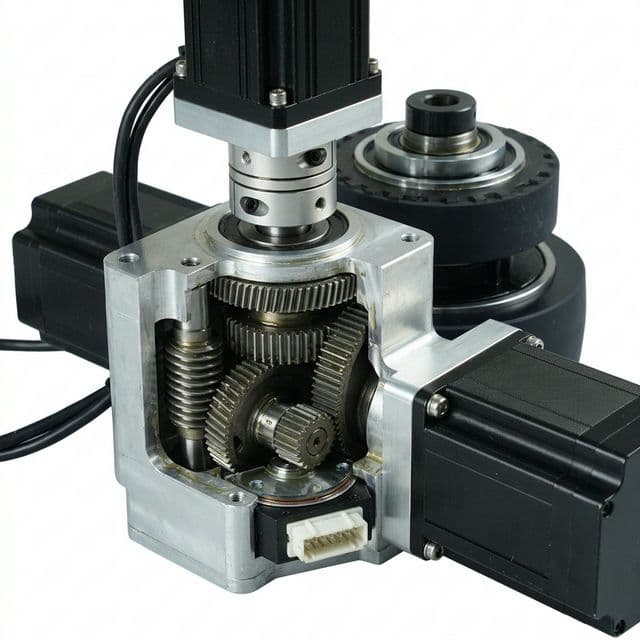
Executive Buyer Summary (reviewed 2026-11-03): Specify an AMR drive unit from its wheel-load spectrum, bearing support geometry, and transmitted torque history. A dock-plate impact requires separate checks for peak-load damage and accumulated fatigue. A sustained 2.5× equivalent load reduces calculated roller-bearing L10h to about 4.7% of its baseline, but a brief 2.5× peak cannot be treated as a continuous load. Use the crossing duration and frequency in the fatigue calculation. For gears, review ISO 6336 tooth bending separately; a radial wheel-force multiplier is not automatically the gear application factor K_A.
Scope: Global procurement and engineering guidance for industrial AMR/AGV drive modules crossing joints, elevator sills, and dock plates. The calculations below are reproducible hypothetical examples, not fleet measurements, product ratings, or service-life guarantees. This guide does not approve a vehicle's permissible obstacle height, braking behavior, or machinery safety compliance. Request a drivetrain RFQ review with your wheel layout, floor profile, speed, and load spectrum.
1. Scope, Operational Boundaries, and Failure Mechanics
Heavy-payload mobile robots encounter floor discontinuities that a static wheel-load figure does not describe. Record gap width, step height, edge shape, crossing direction, payload distribution, and speed before comparing supplier ratings. A dock lip traversable at one load and speed may be unsuitable at another.
Separate three mechanisms in the RFQ:
- Permanent indentation and overload: A short peak may damage bearing contacts, shafts, or housings. Check the bearing's equivalent static load P_0 and static safety factor s_0 = C_0 / P_0 against the manufacturer's application requirements. Static load ratings also matter for short shock loads during rotation.
- Rolling-contact fatigue: Use each bearing's equivalent dynamic load P over the rotating duty cycle. ISO 281 basic rating life describes a population fatigue metric; it does not predict the date when an individual module will fail.
- Deflection and gear loading: Wheel overhang can amplify bearing reactions and deform the support system. Whether that deformation affects a gear mesh depends on the actual shaft, carrier, bearing, and housing arrangement.
Do not combine indentation, fatigue spalling, and gear fracture into one inevitable failure sequence. They need different evidence and acceptance limits.
2. Dynamic Impact Inputs: Separate Wheel Shock from Gear K_A
Use a distinct symbol for the radial wheel-force ratio:
K_r = F_r,peak / F_r,stat
F_r,peak = K_r × F_r,stat
K_r is a label used in this guide, not a standardized dock-plate factor. Gear K_A describes external loading of the gear transmission; establish it from the torque history and the selected gear-rating method. Applying the same multiplier to wheel load and transmitted torque can misrepresent the load path or count an overload twice.
What to Measure Before Assigning a Shock Load
Step height and horizontal speed alone cannot establish peak force. Tire geometry, load-deflection behavior, damping, wheel radius, suspension travel, and effective moving mass all affect the pulse. Shore hardness alone does not specify tire stiffness.
Record force with a calibrated load path or infer it through a validated dynamic model. If using accelerometers, document sensor location, axes, bandwidth, sampling rate, filtering, and gravity treatment. A hub acceleration peak is not automatically a wheel-load multiplier or chassis acceleration. Capture pulse duration and crossings per mission as well as the maximum.
Floor-Condition Evidence Matrix
This is a measurement plan, not an empirical table of universal shock factors or allowable crossing speeds.
| Floor / Transition Condition | Geometry to Record | Operating Variables | Load Evidence to Request | Procurement Decision |
|---|---|---|---|---|
| Smooth reference floor | Roughness and local level changes | Loaded wheel force, speed, tire temperature | Baseline force and vibration trace | Establish the reference duty bin |
| Concrete expansion joint | Gap width, depth, edge radius | Crossing angle and crossings per shift | Peak force and pulse duration | Include repeated crossings in the spectrum |
| Damaged or spalled joint | Broken-edge profile and maximum drop | Route variation and payload position | Worst credible profile plus repeatability | Repair floor or qualify a restricted route |
| Steel deck transition | Step, gap, plate thickness and support | Plate motion and crossing speed | Wheel force with plate deflection | Review fasteners and support stiffness |
| Elevator sill | Gap, height mismatch and track profile | Elevator leveling variation and direction | Loaded and unloaded crossings | Agree a vehicle-level crossing limit |
| Dock leveler / dock plate | Lip profile, ramp angle, plate movement | Load, approach speed and braking state | Synchronized force, torque and speed traces | Check peak integrity and fatigue separately |
| Outdoor ramp / rough pavement | Pothole profile, slope and debris | Wet conditions, steering and temperature | Multi-axis loads and tire condition | Confirm environmental and route limits |
3. ISO 281 Rating Life: The Non-Linear Load Penalty
ISO 281:2007 defines basic rating life at 90% reliability under its stated conditions. NSK's load-rating guidance explains the following load-life relationship:
L_10  = (C / P)^p                         [million revolutions]
L_10h = 10^6 / (60 × n) × (C / P)^p       [hours at constant speed]

p = 3 for ball bearings
p = 10/3 for roller bearings
C is the bearing's basic dynamic load rating, P its equivalent dynamic load in the same force units, and n the rotational speed of that bearing in rpm. A motor-side bearing does not run at wheel speed.
For a radial bearing, determine P using the manufacturer's radial/axial load factors and arrangement rules; it is not always equal to the wheel force. Include induced axial loads where applicable, preload, and internal gear forces. Modified rating life also requires lubrication, contamination, and reliability inputs. Basic L10h does not cover every damage mechanism, including corrosion or electrical erosion.
Sustained Load Increase Versus a Short Peak
At unchanged speed and C, increasing the equivalent load throughout operation by a factor K changes the basic life by K^(-p). For roller bearings, a sustained 2.5× increase gives:
Life ratio = (1 / 2.5)^(10/3) = 0.04716
Illustrative baseline: 30,000 h × 0.04716 ≈ 1,415 h
That is a sensitivity calculation, not a prediction for a robot that occasionally crosses a dock plate. For discrete rotating load bins, use revolution fractions:
q_i = n_i × t_i / sum(n_j × t_j)
P_eq = [sum(q_i × P_i^p)]^(1/p)
At constant speed, q_i equals the fraction of rotating time. With varying speed, use revolution weighting and a corresponding average speed to convert life to hours, or calculate fatigue consumption by bin. A stationary impact still needs a peak/static integrity check even though it contributes no rolling revolutions. This simplified spectrum method assumes conventional rolling fatigue and cannot represent plastic impact damage.
Equivalent Bearing Reactions with Cantilever Moments
For a simplified shaft with two radial supports separated by S, and a downward wheel force F acting at distance L beyond the outer support:
Outer reaction magnitude: R_2 = F × (1 + L/S), upward on the shaft
Inner reaction magnitude: R_1 = F × L/S, downward on the shaft
Overhang moment magnitude at the outer support: M = F × L
These are rigid-body equilibrium results, not a full bearing stiffness model. For F = 12,500 N and L/S = 1.2, R_2 = 27,500 N and R_1 = 15,000 N. Bearing forces on the housing act in the opposite directions. Use effective load centers for angular-contact or tapered arrangements; the physical ring centerlines may not be the correct support locations.
R_2 is an input to bearing selection. It is not a minimum catalogue C rating: the required C depends on target life, speed, load spectrum, and the actual equivalent load.
4. Bearing Topology Comparison for AMR Drive Hubs
Compare complete arrangements at the same packaging and duty conditions. Bearing type or vehicle mass alone cannot approve or disqualify a design.
| Bearing Arrangement | Useful Characteristic | Moment / Axial Consideration | Main Trade-off | Evidence for RFQ Review |
|---|---|---|---|---|
| Two deep groove ball bearings | Simple, widely available support | Span, clearance and axial load affect stiffness | May need a larger envelope for the duty | Exact C/C_0, fits, clearance and load calculation |
| Back-to-back angular-contact pair | Effective support spread can improve tilt stiffness | Contact angle and preload govern combined loads | Assembly and thermal sensitivity | Effective load centers and preload range |
| Face-to-face angular-contact pair | Alternative combined-load arrangement | Usually less moment leverage for comparable geometry | Suitability depends on shaft/housing movement | Stiffness and misalignment assessment |
| Paired tapered roller bearings | Combined radial/axial load capability | Setting affects stiffness, friction and temperature | Preload/endplay control and lubrication | Manufacturer setting procedure and induced thrust calculation |
| Crossed roller cartridge | Compact moment-supporting arrangement | Mounting-ring stiffness is important | Housing accuracy and installation demands | Rated loads, moment limits and mounting requirements |
| Two spaced spherical roller bearings | Can accommodate specified misalignment | Support span and locating scheme remain necessary | Packaging and system tilt control | Permitted misalignment, axial location and load distribution |
The life exponent p is not a shock-resistance score. Check actual ratings, contact loading, assembly tolerances, seals, lubrication, and the supplier's peak-load limits. Avoid universal mass cutoffs, fixed preload values, or percentage capacity advantages without matched catalogue evidence.
5. Cantilever Deflection and ISO 6336 Gear Fatigue
ISO 6336-3:2019 addresses tooth bending strength of qualifying involute spur and helical gears. It does not approve the entire gearbox against every failure mode.
A simplified factor relationship helps organize a supplier report:
sigma_F = sigma_F0 × K_A × K_V × K_Fbeta × K_FalphaHere sigma_F0 is nominal tooth-root stress, K_A the external application factor, K_V the internal dynamic factor, K_Fbeta the face load factor, and K_Falpha the transverse load factor. A complete calculation also needs geometry, material condition, life and other relevant factors, and planetary load-sharing assumptions. Ask whether measured peak torque is already included before adding K_A.
Output support deflection can change gear alignment, but there is no universal arcminute threshold that maps directly to K_Fbeta. Obtain shaft, bearing, housing, and carrier stiffness calculations for the actual mesh. Gear face width, lead modifications, manufacturing errors, and load sharing all affect the result. An isolated cantilever formula is insufficient for a two-bearing gearbox assembly.
A Factor Sensitivity Example, Not a Gear Approval
Assume sigma_F0 = 145 MPa, gear K_A = 1.4, K_V = 1.10, and K_Falpha = 1.12. These inputs are hypothetical and independent of the radial wheel K_r used later.
At assumed K_Fbeta = 1.20: sigma_F = 300.1 MPa
At assumed K_Fbeta = 2.45: sigma_F = 612.7 MPa
If a supplier-derived permissible stress sigma_FP were 480 MPa, already incorporating the agreed minimum safety requirement, the stress utilizations would be 0.63 and 1.28 respectively. The latter exceeds that assumed limit; neither result establishes a failure time or a complete ISO 6336 approval. Do not call sigma_FP / sigma_F an additional safety factor when the minimum safety factor is already included in sigma_FP.
Request the reported bending safety factor S_F, its exact definition, and the agreed minimum from the full rating calculation. A target such as S_F ≥ 1.5 can be a project RFQ requirement; it is not a universal ISO mandate for AMR drive units. Check pitting, scuffing, shaft strength, and single-event overload separately. Motor current limiting affects transmitted torque but does not by itself cap radial impact force.
6. Engineering Visual: Cantilever Shock Load and Bearing Reactions
The schematic uses the simplified equilibrium model from Section 3. It shows forces on the shaft; dimensions and support stiffness are illustrative.
The larger outer reaction follows from geometry. The drawing does not determine bearing type, carrier tilt, or gear fatigue life.
7. Hardware Inspection: What a Gearbox Cutaway Can Show
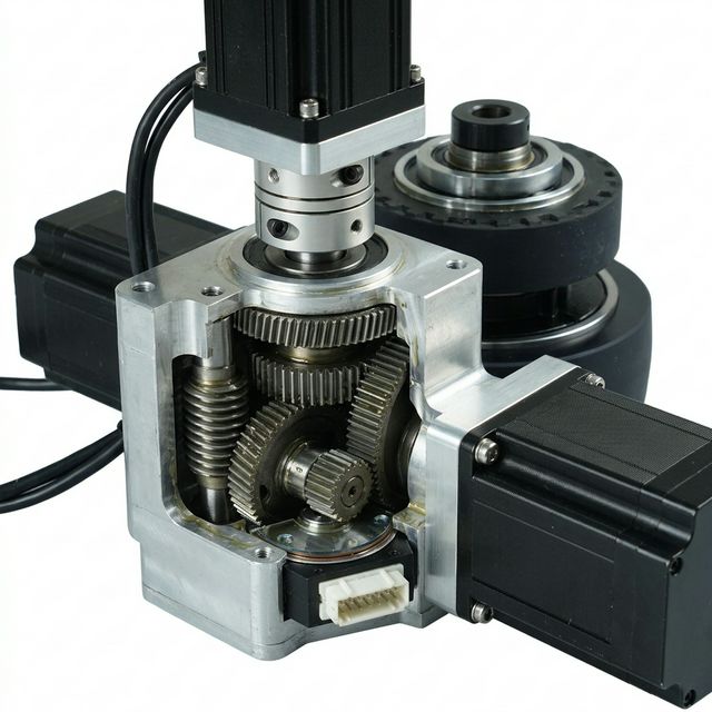
For a candidate module, request a section drawing that identifies the wheel load plane, effective bearing span, torque path, and service access. Match that drawing to the quoted revision and bearing BOM.
- Suspension and floating linkages: AMR suspension sourcing guide for support-load and travel questions.
- Tire selection: AMR drive wheel material guide for compound and thermal-duty questions.
- Product discussion: Heavy-payload drive units for packaging and load requirements to confirm in a project quotation.
8. Sizing Framework: A Hypothetical 2,400 kg AGV Example
This arithmetic example compares assumed candidate ratings. It is not a customer case study or a catalogue claim. No bearing part numbers or supplier performance are implied.
Baseline Parameters
- Loaded vehicle mass: 2,400 kg, with two drive wheels and four supporting casters.
- Assumed static load per drive wheel: 7,850 N; the remaining weight is carried by the casters. Actual load sharing needs measurement or a chassis model.
- Wheel diameter D: 0.250 m; constant travel speed v: 1.4 m/s.
- Wheel-bearing speed n = 60v / (πD) = 106.95 rpm, excluding stops and slip.
- Effective support span S: 110 mm; overhang L: 145 mm.
- Assumed radial load ratios: K_r = 1.3 in the baseline bin and K_r = 2.6 in the peak bin. Neither value is derived from a dock profile or an ISO table.
- Simplification for arithmetic: P equals the outer support's radial reaction. Axial loads, preload, gear forces, and bearing-specific correction factors are omitted and must be restored for a real selection.
Step 1: Calculate the Support Reactions
L/S = 145/110 = 1.31818
Peak wheel force = 2.6 × 7,850 = 20,410 N
Outer peak reaction = 20,410 × (1 + 145/110) = 47,314 N
Inner peak reaction = 20,410 × (145/110) = 26,904 N
Outer baseline reaction = 1.3 × 7,850 × (1 + 145/110) = 23,657 N
Check P_0 and the actual candidate C_0 against the peak condition independently. No static/overload approval is possible here because those ratings and requirements have not been supplied.
Step 2: Compare Fatigue with Explicit Duty Fractions
Candidate A has an assumed C = 63.7 kN and p = 3. Candidate B has an assumed C = 118.0 kN and p = 10/3. The difference reflects both rating and exponent; it does not isolate a bearing-type advantage.
Compare a baseline-only reference, a peak load occupying 1% of rotating revolutions, and a deliberately severe 25% peak fraction. These fractions are inputs to measure, not route recommendations.
P_eq = [(1 − q) × 23,657.045^p + q × 47,314.091^p]^(1/p)
L_10h = 10^6 / (60 × 106.9521) × (C / P_eq)^p| Candidate | Assumed C | Exponent p | Peak Revolution Fraction q | P_eq | Calculated Basic L10h |
|---|---|---|---|---|---|
| A | 63.7 kN | 3 | 0% (reference) | 23.66 kN | 3,042 h |
| B | 118.0 kN | 10/3 | 0% (reference) | 23.66 kN | 33,042 h |
| A | 63.7 kN | 3 | 1% | 24.20 kN | 2,843 h |
| B | 118.0 kN | 10/3 | 1% | 24.28 kN | 30,292 h |
| A | 63.7 kN | 3 | 25% | 33.14 kN | 1,106 h |
| B | 118.0 kN | 10/3 | 25% | 33.75 kN | 10,105 h |
Buyer decision: If the project requires at least 20,000 h basic L10h under this simplified calculation, B clears the fatigue screen at 1% peak exposure but fails it at 25%; A fails both. B remains unapproved until peak integrity, combined loads, lubrication, assembly, and physical validation are resolved. These hours are not warranty durations or individual failure predictions.
Step 3: Request a Separate Gear Report
Supply synchronized motor/output torque and radial-force histories, gear ratio, efficiency assumptions, reversals, and emergency-stop cases. The Section 5 sensitivity example explains why support stiffness matters, but it cannot derive a gear rating from the vehicle mass or the assumed K_r = 2.6. Reject a report that silently uses this radial multiplier as gear K_A or omits planetary load sharing.
Send the load spectrum and section drawing for an RFQ discussion before comparing candidate prices on a shared life target.
9. OEM Procurement Checklist: Six RFQ Acceptance Gates
Agree numerical limits with the responsible engineers for the actual application. The following deliverables make different quotations comparable without prescribing one bearing architecture.
Gate 1: Application and Load Evidence
- Record loaded/unloaded wheel reactions, payload position, tire condition, floor geometry, speed, crossing counts, and peak-pulse duration.
- Separate radial K_r assumptions from gear K_A; identify the source and owner of each input.
- Define allowable peak force and moment, and the response to an out-of-scope route condition.
Gate 2: Bearing Integrity and ISO 281 Life
- Provide exact manufacturer/designation, C, C_0, clearance or setting, fits, and equivalent-load method for each bearing.
- Submit peak/static checks using P_0 and the agreed s_0 requirement, including moments and axial loads.
- Calculate L10h with revolution-weighted duty bins and the specified reliability/lubrication method; state the project life target.
Gate 3: Shaft, Carrier and Housing Stiffness
- Provide effective support locations and wheel overhang on a revision-controlled drawing.
- Supply analytical or FEA deflection results with load cases, material properties, boundary conditions, and contact assumptions.
- Relate predicted gear misalignment to the actual mesh design and its accepted limits.
Gate 4: Gear Rating and Overload
- Provide the applicable ISO 6336 calculation scope, torque spectrum, gear geometry, material/heat treatment, and load-sharing assumptions.
- State bending and contact safety definitions, agreed minima, and how application/dynamic factors avoid counting the same peak twice.
- Check single-event overload and reversals separately; document any torque-limiting assumptions and their validation.
Gate 5: Lubrication, Sealing and Service
- Specify lubricant, viscosity at operating temperature, compatibility, fill quantity, and maintenance interval with supplier justification.
- Match sealing and ingress requirements to the environment and moving interfaces; identify test evidence for the quoted configuration.
- Define inspection access, replacement parts, setting procedure, and acceptable post-service condition.
Gate 6: Physical Validation and Production Evidence
- Agree a representative crossing or bench-test profile: force/torque histories, speed, payload, cycles, sample count, and environmental conditions.
- Set before/after limits for play, torque-to-turn, noise/vibration, temperature, leakage, and structural damage; retain teardown evidence where required.
- Link serial-number inspection records and change-control rules to the validated BOM. A generic acceleration-only test does not establish a wheel-force rating.
10. Frequently Asked Questions
Can suspension eliminate bearing shock loads?
Suspension can change transmitted loads, but its effect depends on travel, damping, tire compliance, and impact frequency. Measure the assembled module under the specified crossing conditions. Keep both peak-integrity and fatigue checks after adding suspension.
Are deep groove ball bearings unsuitable for heavy AMRs?
There is no universal vehicle-mass cutoff. Compare exact ratings, effective support span, clearance, stiffness, axial loads, and target life. A sufficiently sized ball-bearing arrangement may qualify; a poorly set roller-bearing arrangement may fail its requirements.
What is the ideal overhang-to-span ratio?
In the simplified model, reducing L/S reduces outer reaction for a given wheel force. There is no universal maximum of 1.0 or 1.4. Packaging, effective load centers, shaft/housing stiffness, and actual ratings determine whether a proposed ratio is acceptable.
Can tire Shore hardness predict impact force?
No. Request load-deflection and damping information for the actual diameter, tread thickness, compound, temperature, and speed. A compound change also needs checks for rolling resistance, heating, wear, and available traction.
Must planetary gears have a fixed amount of lead crowning?
No. Lead modifications can manage contact distribution, but their shape and amount must suit the load, alignment, manufacturing tolerances, and gear geometry. Request a design-specific contact assessment rather than prescribing a universal micrometre value.
How should factory acceptance detect impact damage?
Agree repeatable baseline and post-test inspections. Play, torque-to-turn, vibration and temperature measurements can flag changes, but no single FFT measurement proves the absence of indentation or validates long-term life. Define operating conditions, reference limits, and teardown criteria before testing.
Does regenerative braking make every dock crossing the worst load case?
Not necessarily. Braking torque and radial impact may coincide, so capture their timing and review credible combined cases. Any control change must preserve required stopping behavior. Current limiting does not directly limit the wheel's radial impact force.
Is basic L10h a maintenance interval or warranty promise?
No. It is a statistical fatigue rating under stated assumptions. Maintenance and warranty terms must also account for lubrication, contamination, wear, corrosion, overload damage, service access, and the agreed operating envelope.
11. Sources and Technical References
Source identities and public scope statements checked on 2026-11-03. ISO catalogue pages identify the standards; they do not replace the licensed text or a complete application calculation. The examples and RFQ framework above are editorial analysis, with hypothetical inputs explicitly identified.
- ISO 281:2007 — Rolling bearings: Dynamic load ratings and rating life. Official scope for basic and modified rating life, including the 90% reliability basis and exclusions such as wear, corrosion, and electrical erosion. Record the edition used in the supplier report.
- ISO 6336-3:2019 — Calculation of tooth bending strength. Official scope for applicable involute spur/helical gear tooth bending calculations; the scope does not cover every possible gear failure mode.
- NSK — Dynamic Load Ratings and Fatigue Life. Manufacturer explanation of C, equivalent dynamic load P, the ball/roller life exponents, and load-life sensitivity.
12. Next Steps: Drivetrain RFQ Review
Prepare one application sheet containing wheel loads, support dimensions, speed and torque histories, floor profiles, crossing frequency, environment, and required life/reliability. Ask each supplier to identify assumptions and missing evidence before comparing prices.
- Product selection: Review heavy-payload drive unit options and confirm the quoted module's bearing arrangement, ratings, and test scope.
- Steering integration: Use the AGV drive steer unit guide to frame steering, mounting, and service interfaces.
- Project inquiry: Contact our team with the application sheet and request the calculation and validation deliverables in Section 9. Confirm the scope of engineering support and project commitments in the quotation.